1Overview
The Model 12100 Series is a family of compact, USB-powered RF average power sensors. They plug into a host computer and run with no external meter, no cable harness, and no manual zeroing or pre-use calibration. Setup takes minutes, so measurements start almost immediately whether the work happens on the bench or in the field.
Each sensor measures true-RMS average power across any modulation format, including 802.11ac, GSM, CDMA2000, IS-95, TDMA, OFDM, multi-tone, QAM, and CW. Coverage spans 9 kHz to 67 GHz with a dynamic range of -60 to +26 dBm, so the family reads both subtle and high-level signals with traceable accuracy. Patented thermal-stability technology holds readings steady over the full operating range without drift, and deep internal memory with internal or external triggering supports long-term logging.
2Model Selection
The family covers eight frequency tiers. Most tiers ship in two builds: the S suffix is the Standard build starting at 1 MHz, the L suffix is the Extended build starting at 9 kHz. The 12154L and 12167L ship as Extended (L) only. The standard connector is set by the model.
| Model | Frequency range | Standard connector |
|---|---|---|
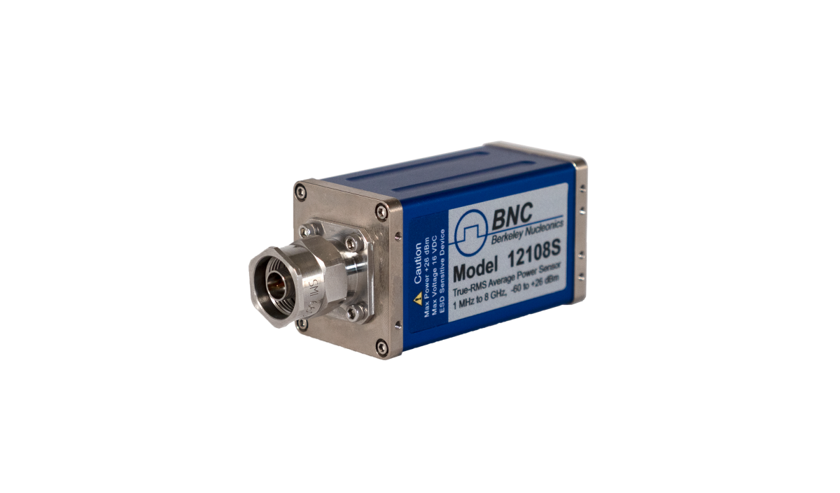
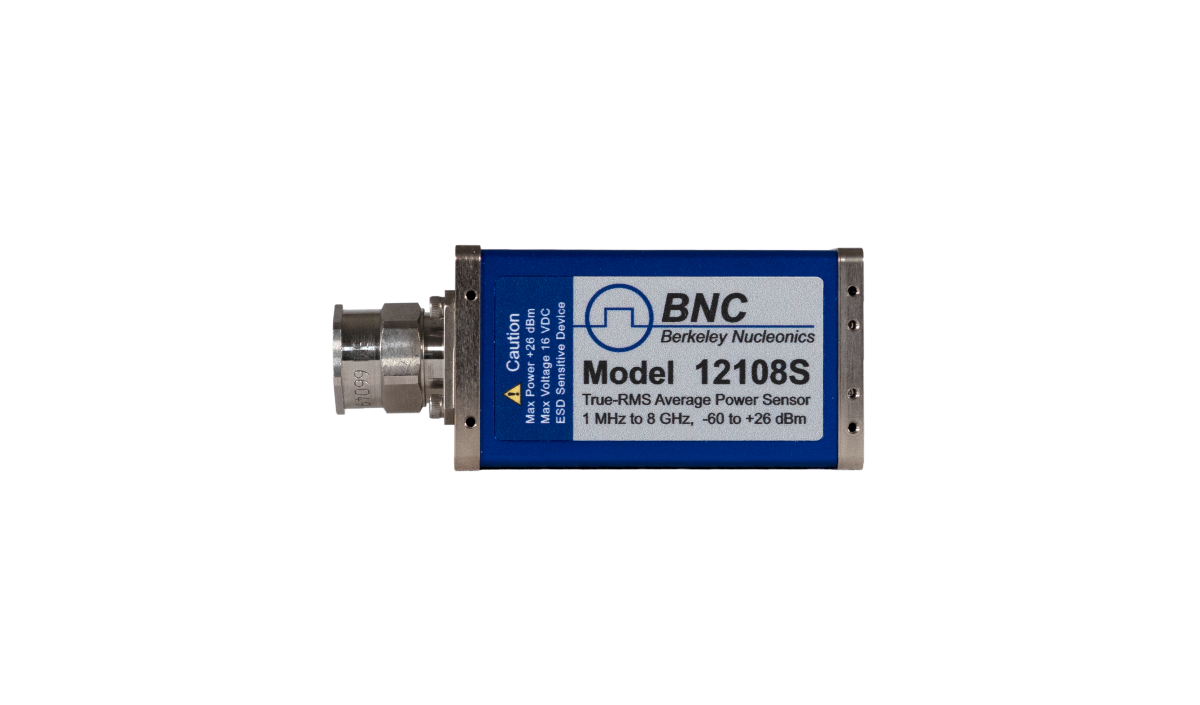
| 12108L | 9 kHz to 8 GHz | Type-N male |
| 12108S | 1 MHz to 8 GHz | Type-N male |
| 12118L | 9 kHz to 18 GHz | Type-N male |
| 12118S | 1 MHz to 18 GHz | Type-N male |
| 12126L | 9 kHz to 26.5 GHz | 3.5 mm male |
| 12126S | 1 MHz to 26.5 GHz | 3.5 mm male |
| 12140L | 9 kHz to 40 GHz | 2.92 mm male |
| 12140S | 1 MHz to 40 GHz | 2.92 mm male |
| 12144L | 9 kHz to 44 GHz | 2.4 mm male |
| 12144S | 1 MHz to 44 GHz | 2.4 mm male |
| 12150L | 9 kHz to 50 GHz | 2.4 mm male |
| 12150S | 1 MHz to 50 GHz | 2.4 mm male |
| 12154L | 9 kHz to 54 GHz | 2.4 mm male |
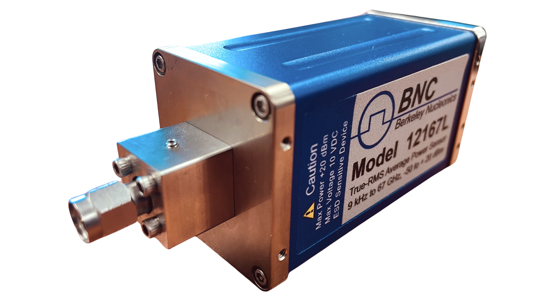
| 12167L | 9 kHz to 67 GHz | 1.85 mm male |
S = Standard (from 1 MHz). L = Extended (from 9 kHz). The dynamic range is -60 to +26 dBm across the family. The 12167L carries a lower continuous-average ceiling and reduced peak limits; see Specifications.
3Key Features
- True-RMS responding and modulation independent across all formats.
- USB plug-and-play operation: no zeroing, no pre-use calibration, no external meter.
- 9 kHz to 67 GHz coverage with a -60 to +26 dBm dynamic range.
- Patented thermal stability holds measurements steady with no drift over the full range.
- Full dynamic range processed with each sample.
- Interfaces: USBTMC and USB HID, with optional SPI or I2C TTL for direct and embedded control.
- IEEE 488.2 SCPI command set, command-compatible with the Agilent U2000 family.
- Extensive internal memory for trace capture and long-term logging.
- Real-time clock with backup, plus optional unattended autonomous operation (UOP).
- Security options: MIL (write-lock) and SEC (secure erase).
4Specifications
| Parameter | Specification |
|---|---|
| Frequency range | 9 kHz to 67 GHz (model dependent; S builds from 1 MHz, L builds from 9 kHz) |
| Input power | -60 to +26 dBm |
| Continuous average | +26 dBm (400 mW); 12167L: +18 dBm (63 mW) |
| Continuous average damage level | +29 dBm (800 mW); 12167L: +23 dBm (200 mW) |
| Peak power | +23 dBm (200 mW); 12167L: +26 dBm (400 mW). Damage level: 36 dBm (4 W) |
| Energy per pulse | 20 W-us; 12167L: 5 W-us. Damage level: 40 W-us; 12167L: 10 W-µs |
| Maximum DC input | Low: 10 VDC (on the RF input); Standard: 16 VDC (on the RF input) |
| Typical VSWR | 12108L/12108S/12118L: < 1.1:1; 12118S: < 1.10:1; 12126L: < 1.14:1; 12126S: < 1.28:1; 12140L/12144L/12144S: < 1.28:1 @ 40 GHz; 12150L/12150S: < 1.39; 12154L: <1.28:1 @ 44 GHz, <1.94:1 @ 54 GHz; 12167L: <1.43:1 @ 67 GHz |
| Typical total RSS error | 12108L: 1.31%; 12108S: 1.09%; 12118L/12118S: 1.3% @ 15 GHz; 12126L: 1.71% @ 18 GHz; 12126S/12140L/12140S: 2.87% @ 30 GHz; 12144L/12144S: 2.77% @ 44 GHz; 12150L/12150S: 2.77% @ 50 GHz; 12154L: 2.77% @ 44 GHz, 3.73% @ 54 GHz; 12167L: 2.77% |
| Standard connector | 12108L/12108S/12118L/12118S: Type-N male; 12126L/12126S: 3.5 mm male; 12140L/12140S: 2.92 mm male; 12144L/12144S/12150L/12150S/12154L: 2.4 mm male; 12167L: 1.85 mm male |
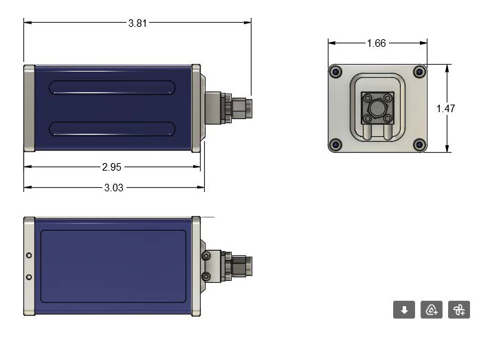
| Dimensions | 1.51 x 1.51 x 3.95 in (verify against released outline drawing) |
| Recommended calibration cycle | 1 year |
Note 1: Pulse repetition must respect average power over any one pulse duty cycle, regardless of varying duty cycle.
5VSWR Specifications
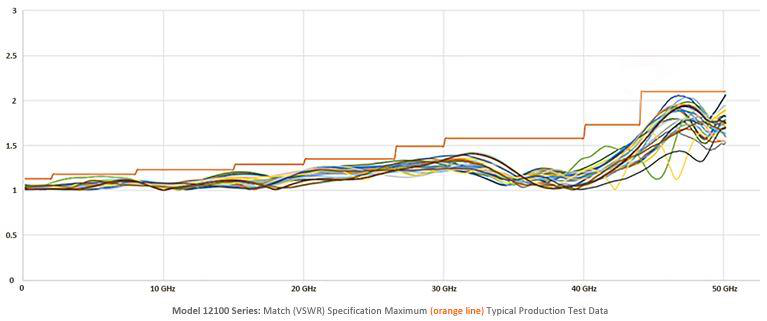
Match is specified per connector type and frequency band. VSWR limits below are stated as the maximum value over each band.
12100L Series (Type-N male)
| Model | Band | VSWR (max) |
|---|---|---|
| All 12100L Series | 9 kHz to 15 kHz | 1.45 |
| 15 kHz to 40 kHz | 1.25 | |
| 40 kHz to 2 GHz | 1.13 | |
| 2 GHz to 8 GHz | 1.18 | |
| 12118L and above | 8 GHz to 15 GHz | 1.23 |
| 15 GHz to 18 GHz | 1.29 | |
| 12126L and above (3.5 mm) | 8 GHz to 18 GHz | 1.23 |
| 18 GHz to 24.5 GHz | 1.30 | |
| 24.5 GHz to 26.5 GHz | 1.35 | |
| 12140L and above (2.92 mm) | 26.5 GHz to 30 GHz | 1.49 |
| 30 GHz to 40 GHz | 1.58 | |
| 12144L (2.4 mm) | 40 GHz to 44 GHz 1 | 1.73 |
| 12150L | 44 GHz to 50 GHz | 1.39 |
| 12154L | 50 GHz to 54 GHz | 2.20 |
12100S Series (Type-N male)
| Model | Band | VSWR (max) |
|---|---|---|
| 12108S and above | 1 MHz to 2 GHz | 1.13 |
| 2 GHz to 8 GHz | 1.18 | |
| 12118S | 8 GHz to 15 GHz | 1.23 |
| 15 GHz to 18 GHz | 1.29 | |
| 12126S (3.5 mm) | 8 GHz to 18 GHz | 1.23 |
| 18 GHz to 24.5 GHz | 1.30 | |
| 24.5 GHz to 26.5 GHz | 1.35 | |
| 12140S and above (2.92 mm) | 15 GHz to 20 GHz | 1.29 |
| 20 GHz to 26.5 GHz | 1.35 | |
| 26.5 GHz to 30 GHz | 1.49 | |
| 30 GHz to 40 GHz | 1.58 | |
| 12144S (2.4 mm) | 40 GHz to 44 GHz | 1.73 |
| 12150S | 44 GHz to 50 GHz | 1.39 |
| 12167L | 50 GHz to 67 GHz | 1.43 |
Note 1: Band annotation carried from the source table.
6Calibration Factor & Linearity
Calibration Factor Uncertainty is stated with coverage factor K=2. Values are grouped by connector type and model range.
12100L Series
| Models / connector | Band | Cal Factor Unc (K=2) |
|---|---|---|
| 12108L – 12140L (Type-N) | 9 kHz to 15 kHz | 2.88% |
| 40 kHz to 2 GHz | 2.23% | |
| 2 GHz to 8 GHz | 2.45% | |
| 12118L – 12140L (Type-N) | 10 GHz to 18 GHz | 2.85% |
| 12126L / 12140L (3.55 mm) | 18 GHz to 26.5 GHz | 2.9% |
| 12140L (2.9 mm) | 26.5 GHz to 30 GHz | 3.42% |
| 30 GHz to 40 GHz | 3.9% | |
| 12144L / 12150L (2.4 mm) | 9 kHz to 40 kHz | 2.88% |
| 40 kHz to 2 GHz | 2.23% | |
| 2 GHz to 8 GHz | 2.45% | |
| 10 GHz to 18 GHz | 2.85% | |
| 18 GHz to 26.5 GHz | 2.9% | |
| 26.5 GHz to 30 GHz | 2.65% | |
| 30 GHz to 40 GHz | 2.82% | |
| 40 GHz to 44 GHz | 2.94% | |
| 44 GHz to 50 GHz | 3.42% | |
| 50 GHz to 54 GHz | 5.81% |
Linearity Uncertainty (12100L Series)
| Input level | Linearity Unc |
|---|---|
| +10 dBm to +20 dBm | 3.0% |
| -10 dBm to +10 dBm | 2.0% |
| -20 dBm to -10 dBm | 3.5% |
| -60 dBm to -20 dBm | 2.0% |
12100S Series
| Models / connector | Band | Cal Factor Unc (K=2) |
|---|---|---|
| 12108S / 12118S (Type-N) | 5 MHz to 2 GHz | 1.79% |
| 2 GHz to 8 GHz | 1.53% | |
| 12118S (Type-N) | 2 GHz to 10 GHz | 1.53% |
| 10 GHz to 18 GHz | 1.78% | |
| 12126S – 12144S (3.5 mm) 1 | 5 MHz to 2 GHz | 2.23% |
| 2 GHz to 10 GHz | 2.45% | |
| 10 GHz to 18 GHz | 2.85% | |
| 18 GHz to 26.5 GHz | 2.9% | |
| 12140S (2.92 mm) 1 | 26.5 GHz to 30 GHz | 3.42% |
| 30 GHz to 40 GHz | 3.9% | |
| 12144S / 12150S (2.4 mm) 1 | 26.5 GHz to 30 GHz | 2.65% |
| 30 GHz to 40 GHz | 2.82% | |
| 40 GHz to 44 GHz | 2.94% |
Linearity Uncertainty (12100S Series)
| Input level | Linearity Unc |
|---|---|
| +10 dBm to +20 dBm | 3.0% |
| -10 dBm to +10 dBm | 2.0% |
| -20 dBm to -10 dBm | 3.5% |
| -60 dBm to -20 dBm | 2.0% |
Cal Factor and Linearity notes (12100S Series): 1. For Normal Mode add 1%. 2. For Normal Mode add 1.5%.
12167L (1.85 mm male)
| Band | Cal Factor Unc (K=2) |
|---|---|
| 9 kHz to 40 kHz | 2.88% |
| 40 kHz to 2 GHz | 2.23% |
| 2 GHz to 10 GHz | 2.45% |
| 10 GHz to 18 GHz | 2.85% |
| 18 GHz to 26.5 GHz | 2.9% |
| 26.5 GHz to 30 GHz | 2.65% |
| 30 GHz to 40 GHz | 2.82% |
| 40 GHz to 44 GHz | 2.94% |
| 44 GHz to 50 GHz | 3.42% |
| 50 GHz to 67 GHz | 5.81% |
7Noise & Zero Offset
Noise Specifications
| Mode / band | Specification | Typical |
|---|---|---|
| Average Mode: -40 dBm to +26 dBm 3 | 0.35% | 0.025% to 0.15% 4 |
| Average Mode: -60 dBm to -40 dBm | 0.5 nW 5 | 0.2 nW 6 |
| Normal Mode 2 ms Gate: +10 dBm to +26 dBm | 0.35% | 0.15% |
| Normal Mode 2 ms Gate: 0 dBm to +10 dBm | 0.5% | 0.25% |
| Normal Mode 2 ms Gate: -8 dBm to 0 dBm | 1.0% | 0.5% |
| Normal Mode 2 ms Gate: -25 dBm to -8 dBm | 1.5% | 0.75% |
| Normal Mode 2 ms Gate: -38 dBm to -25 dBm | 28 nW | 20 nW |
| Normal Mode 2 ms Gate: -45 dBm to -38 dBm | 95 nW | 50 nW |
| Normal Mode 1 us Gate: +10 dBm to +26 dBm | 0.45% | 0.18% |
| Normal Mode 1 us Gate: 0 dBm to +10 dBm | 3% | 2% |
| Normal Mode 1 us Gate: -38 dBm to 0 dBm | 8.5% | 1% to 4% |
Noise notes (12100L Series): 3. Noise is two times the standard deviation of 100 measurement points. 4. Number of averages for each measurement rate: Normal 16; Double 32; Super 384. 5. For Normal measurement rate, when averages above 16 and power is above -40 dBm noise error is insignificant. 6. Varies with power level. 7. Noise is determined by multiplying the value by 4/sqrt(Normal measurement rate averages). Example (Specification): for 1024 averages noise is less than 0.5nW*(4/sqrt(1024)) = 0.063 nW; for 128 averages, 0.5nW*(4/sqrt(128)) = 0.18 nW. 8. Same formula for typical: for 1024 averages 0.2nW*(4/sqrt(1024)) = 0.025 nW; for 128 averages 0.2nW*(4/sqrt(128)) = 0.071 nW.
Zero Offset Specifications
| Model | Parameter | Specification |
|---|---|---|
| All 12100 Series | Zero Offset (Average Mode) | {[(1.0 nW @ 25°C) + |ΔT| x (0.075 nW/°C)] ± 0.01 nW /month} |
| 12100S Series | Zero Offset (Normal Mode) | 50 nW +/- 1 nW/month |
Zero Offset notes (all 12100 Series): 1. Use this formula to determine Zero Offset uncertainty (%): Z = (Zero Offset Power / Measured Power) x 100. 2. Linearity and Zero Offset are measured as a combined specification, as BNC sensors require no meter zeroing or reference calibration before use.
8Temperature & Thermal Stability
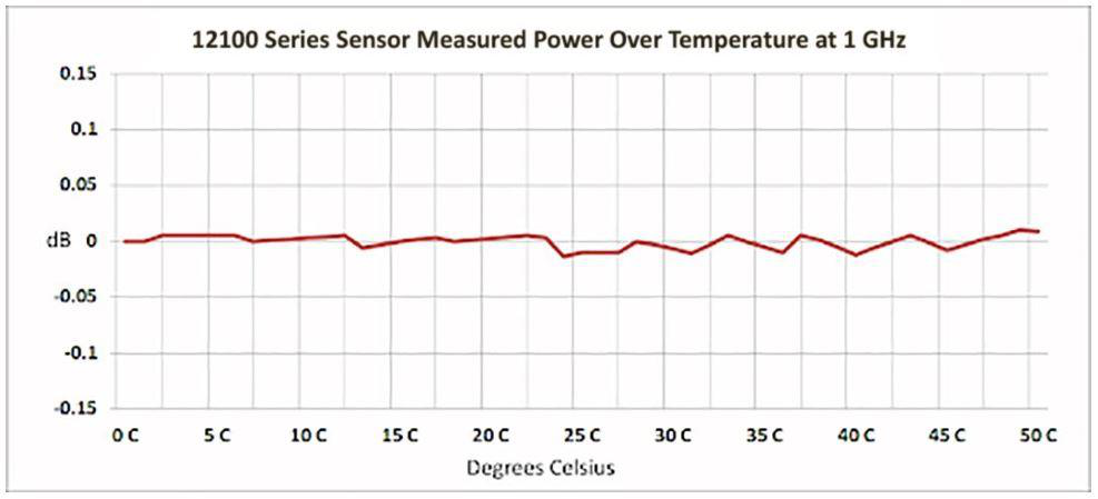
Temperature Uncertainty (Average Mode)
| Range (all 12100 Series) | Specification | Typical |
|---|---|---|
| 40°C to 55°C | 2.5% | 0.5% |
| 30°C to 40°C | 0.5% | 0% |
| 20°C to 30°C | 0% | 0% |
| 10°C to 20°C | 0.5% | 0% |
| 0°C to 10°C | 2.5% | 0.5% |
Temperature Uncertainty (Normal Mode): (verify; not specified in source).
Thermal Stability
BNC thermal-stability technology is built into the Model 12100 Series. Measurements remain stable over the entire operating temperature range with no user intervention, zeroing, or calibration. This patented process also defines the zero-power conditions and eliminates zeroing requirements. Measurements are not interrupted for zeroing or calibration.
9PowerEye Software
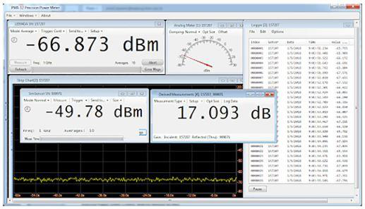
The Model 12100L Series sensors use BNC PowerEye Precision Power Meter software. The software allows users to make a wide variety of measurements from basic average power to complex triggered measurements. Refer to the BNC PowerEye user's manual for further information. In addition to PowerEye, BNC provides an interactive IO utility with source code, a Persona utility, plus a variety of programmatic code and support.
- For use with any 12100 Series sensor.
- Two sensor calculation windows with calculations for Gain, Loss, VSWR, Reflection Coefficient, Mismatch Loss, and Return Loss.
- USB threading increases performance when using multiple sensors.
- Triggering control including setting Level, Delay, Slope, Hysteresis, Impedance, and more.
- Tabular logging with file storage and retrieval.
- Controls Option UOP (Unattended Operation) and Option 001 (Analog Recorder Out).
- Recorder Out (analog out) control for scaling, etc.
- Offset controls including simple offset and frequency-dependent offset tables.
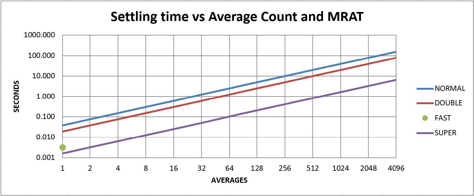
Average Detector Mode Measurement Rate (MRAT), all 12100 Series
| Setting | Normal | Double | Fast | Super |
|---|---|---|---|---|
| Samples per measurement | 384 | 192 | 32 | 16 |
| Number of averages per measurement | 1 to 1024 | 1 to 1024 | 1 | 1 to 4069 |
| Measurement time per average | 38.4 ms | 19.2 ms | 3.2 ms | 1.6 ms |
Normal Detector Mode Video Bandwidth, 12100 Series
| Parameter | Minimum | Typical |
|---|---|---|
| Auto Range | 8 kHz | 10 kHz |
| Averages per Range = 1 (-15 dBm typ. to 26 dBm) | 40 kHz | 60 kHz |
| Range = 0 (-45 dBm to -12 dBm typ.) | 8 kHz | 10 kHz |
10Interfaces & Remote Control
Interface Connectivity
The 12100 Series sensors support both USBTMC and USB HID. Direct control is also possible using optional SPI and I2C interface ports. These functions are optimized for programmatic control as well as unattended and logged power measurements. The sensors can be set up, controlled, and read from any of the connectivity options.
| Interface | Detail |
|---|---|
| USBTMC | USB488 compliant |
| USB HID | USB Human Interface Device Class compliant |
| SPI / I2C (Option SPI) | Cable and connector included with Option SPI. Cable may also power the sensor for unattended applications. |
Remote Programming
The sensor is designed for full programmatic control in ATE systems and other applications requiring remote programming. 12100 Series sensors use SCPI commands; all three connectivity options use the SCPI command set.
| Parameter | Specification |
|---|---|
| Supporting ports | USBTMC, USB HID, SPI/I2C |
| Command set | SCPI (Standard Commands for Programmable Instruments) |
| Compatibility | Compatible with systems using USBTMC programmatic control, NI and Agilent Visa IO libraries, Agilent U2000, and others using the SCPI command set.* |
*Agilent is a trademark of Agilent Technologies Inc; NI is a trademark of National Instruments, Inc.
Analog Recorder Output (Option 001)
Recorder Output is a filtered analog output for various purposes. It provides an accurate scaled voltage representing the power level of the signal. The output is linear (not log dB) and can be scaled. When enabled, Recorder Out uses the same SMB port used by Trigger Out, making the port unavailable for triggering use. Trigger In is not affected.
| Parameter | Specification |
|---|---|
| Output filter bandwidth | Average Detector mode: 0.001 Hz to 32 Hz (settable); Normal Detector mode: 0.001 Hz to 81 Hz (settable) |
| Output range | 0 to 1 Volt into 1,000 Ohms. Note: potential of 2.5 V when set as Recorder Out; or 5 V when used as Trigger Output |
| Output impedance | 1 k Ohms |
| Resolution | +/- 25 µV |
| DC Offset | 0 to 5 mV |
| Scale | Linear |
| Connector | SMB Male (shared with Trigger Out and Wideband Video Out) |
11Triggering
The 12100 Series trigger functions, including slope, level, trigger delay, hold off, and rearm delay, can be set. External trigger input is available for gated measurements, synchronizing multiple sensors, or other purposes. Trigger Input and output use SMB Male connectors, which may be shared with other options.
General
| Parameter | Specification |
|---|---|
| Trigger source | Internal (signal level), Immediate, External / Internal triggering not supported (12144L) |
| Trigger Delay range | +/- 10 Seconds |
| Auto trigger delay | Varies based on resolution setting (Default 45 ms). Average Mode: 11 ms to 61 ms / Trace Mode: 44 us to 244 us (12108S) |
| Resolution | 1 us |
| Trigger Out pulse width | 500 ns |
| Trigger Out level | Maximum ≈ VUSB ≈ 5.5 VDC (typical). Typical high level 4.0 V with 600 ohm load (with VUSB=5.0 V). Max low level 0.8 V. Minimum load resistance 200 ohms. |
Internal Triggering
| Parameter | Specification |
|---|---|
| Level | Settable to approximately -50 dBm to 20 dBm |
| Level resolution | 0.1 dB |
| Slope | Positive or Negative |
| Hysteresis | Settable to 0 dB to 3 dB |
External Triggering
| Parameter | Specification |
|---|---|
| Trigger Input | Min high level 2.0 Volts, Max low level 0.8 Volts |
| Input Load | Selectable 100 kΩ or 50 Ω |
| Timing requirements | Minimum pulse width 25 ns (on), 25 ns (off); Repetition 50 ns (min) |
| Absolute input limits | +5.5 Volts maximum; -0.5 Volts minimum |
12Memory, Logging & Real Time Clock
Store, Recall and Logging Memory
The 12100 Series contains volatile and non-volatile memory. Store and recall functions for the sensor's state and register functions such as Frequency, Averages, and Analog Recorder Out settings have a lifetime of 1 million write and erase cycles. When Option UOP is present, the sensor contains separate non-volatile flash memory designed for long-term logging of measurements.
| Parameter | Specification |
|---|---|
| Non-volatile NAND flash | 50 Million measurements |
| Maximum storage rate | 1000 measurements per second |
Unattended Operation (UOP)
Unattended operation makes autonomous measurements. Once set up using a computer, the sensor only requires power to function. Measurements are stored in non-volatile memory and time stamped using the internal real time clock. The option allows the use of trigger functions. Recorder output can be enabled while in unattended operation, allowing calibrated analog output functions with no computer or power meter connected. Power can be applied using a USB power-only cable or, if Option SPI has been purchased, its ribbon cable. Measurement storage using UOP is not possible when Option MIL is installed.
Real Time Clock
If Option UOP is present, the 12100 Series contains a real time clock used to timestamp logged measurements. When the sensor is powered on, the high-accuracy time base is used to increase the accuracy of the real time clock.
| Parameter | Specification |
|---|---|
| Time Accuracy | Typical: un-powered 20 ppm at 25°C; under power and stable, 2 ppm (disciplined by high-accuracy time-base). Consult the factory for further information. |
| Functionality | Provides timestamp data for measurements stored in memory. When used with Option UOC (unattended operation), can deactivate low power mode, trigger measurements, and activate low power mode. |
| Backup | Super cap. When fully charged, provides 1 day (typical) RTC operation with no power applied to the sensor. Minimum charge time 5 minutes. |
13Environmental & Security
Environmental
| Parameter | Operating | Storage |
|---|---|---|
| Temperature | 0°C to 55°C | -25°C to 85°C |
| Humidity | 15% to 95% non-condensing | 15% to 95% non-condensing |
| Altitude | 10,000 feet (3,000 meters) | 50,000 feet (15,000 meters) |
Initial Stabilization Time
For general use, the 12100 Series sensors are stable 5 minutes after electrical power is applied. Specifications in this datasheet are valid ONLY after a 30 minute warm-up period and for continuous wave (CW) signals unless otherwise stated. The recommended calibration interval is one year. Specifications apply over the listed temperature and relative humidity range unless otherwise stated.
Option MIL
Option MIL addresses security and data sanitization. With this option, the user cannot write to any non-volatile memory. Consult the factory for additional information regarding Option MIL.
Sanitization Option (SEC)
The sanitization option adds secure erase capability. When the SEC command is executed, all non-volatile memory is erased, including User Presets, Persona information, Store and Recall data, User Cal, Simple offsets, and FDO tables. The process is an erase, random overwrite erase process. For additional security, users can execute the command repeatedly. The option is not available if Option MIL is purchased, because non-volatile memory writes are disallowed with that option.
14Applications
- Automated test equipment (ATE).
- Direct control.
- Research and development.
- Manufacturing.
- Radar, satellite, and telecommunications.
15Ordering & Outline Drawings
Specify the model number, which sets both the frequency reach and the standard connector. Choose the S build for coverage from 1 MHz or the L build for coverage from 9 kHz. Add options such as SPI / I2C, Analog Recorder Out (Option 001), Unattended Operation (UOP), and the MIL or SEC security options as the application requires.
| Model | Standard connector |
|---|---|
| 12108S / 12108L / 12118S / 12118L | Type-N male |
| 12126S / 12126L | 3.5 mm male |
| 12140S / 12140L | 2.92 mm male |
| 12144S / 12144L / 12150S / 12150L / 12154L | 2.4 mm male |
| 12167L | 1.85 mm male |
Outline Drawings
Available Options & Accessories
- ATE mounting bracket (also shown with SPI cable).
- Secure USB cable.
- SPI / I2C (Option SPI).
- Demonstration kit available.
- Optional connectors available.
| Contact | Detail |
|---|---|
| info@berkeleynucleonics.com | |
| Phone | (415) 453-9955 |
| Quote / demo | berkeleynucleonics.com/get-quote |