1Overview
The RFS-1220 and RFS-1420 are compact, high-performance RF and microwave signal generators designed for lab testing, automated systems, and RF development. Offering precise frequency control, low phase noise, and a broad operating range, these generators provide a cost-effective solution for engineers and researchers. The small, portable aluminum enclosure is ideal for both lab and field use.
Two models share the same mechanical footprint. The RFS-1220 covers 0.1 GHz to 20 GHz calibrated, settable to 22 GHz. The RFS-1420 extends coverage to 40 GHz calibrated, settable to 42 GHz. Both run on USB-C power (no bulky DC adapters required) and accept USB and Ethernet control over SCPI.
2Key Features
- Wide frequency coverage: 0.1 GHz to 42 GHz
- Compact and ruggedized design: small, portable aluminum enclosure ideal for lab and field use
- High output power: up to +15 dBm with fine power control
- Low phase noise: excellent spectral purity for demanding applications
- Precision frequency control: ultra-fine tuning with small frequency step sizes (< 2 Hz or 10 Hz)
- Dual powering options: USB-C powered (no bulky DC adapters required)
- Control over USB and Ethernet using SCPI commands
3Frequency & Output Power
The RFS-1220 delivers up to +15 dBm across its range, with a level window from -40 dBm at low band. The RFS-1420 carries that high output to 40 GHz. Power output accuracy is ±1.0 dB typical on the RFS-1220, and on the RFS-1420 holds to ±1.0 dB from LF to 20 GHz and ±2.0 dB from 20 to 40 GHz.
| Model | Frequency range | Output power range |
|---|---|---|
| RFS-1220 | 0.1 to 20 GHz calibrated, settable to 22 GHz | -40 to +15 dBm (0 to 13 GHz); -22 to +15 dBm (13 to 22 GHz) |
| RFS-1420 | 0.1 to 40 GHz calibrated, settable to 42 GHz | -20 to +13 dBm (0.1 to 20 GHz); -13 to +15 dBm (20 to 40 GHz) |
4Phase Noise & Spectral Purity
Phase noise is specified at the top of each model's range, where it is hardest to hold.
| Carrier | Offset | SSB phase noise |
|---|---|---|
| 20 GHz (RFS-1220) | 10 kHz | -92 dBc |
| 40 GHz (RFS-1420) | 10 kHz | -90 dBc |
Harmonics measure < -25 dBc typical on both models.
5Frequency Switching & Agility
Precision frequency control gives ultra-fine tuning with small frequency step sizes: < 2 Hz on the RFS-1220 and 10 Hz on the RFS-1420. Frequency is set over SCPI command through USB or Ethernet.
6Modulation
Modulation modes are not stated in the datasheet.
7Product Comparison
| Feature | RFS-1220 (22 GHz) | RFS-1420 (42 GHz) |
|---|---|---|
| Frequency range | 0.1 to 20 GHz (calibrated); 0.1 to 22 GHz (settable) | 0.1 to 40 GHz (calibrated); 0.1 to 42 GHz (settable) |
| Output power range | -40 to +15 dBm (0 to 13 GHz); -22 to +15 dBm (13 to 22 GHz) | -20 dBm to +13 dBm (0.1 to 20 GHz); -13 dBm to +15 dBm (20 to 40 GHz) |
| Power output accuracy | ±1.0 dB typical | ±1.0 dB (LF to 20 GHz); ±2.0 dB (20 to 40 GHz) |
| Phase noise | -92 dBc @ 20 GHz (10 kHz offset) | -90 dBc @ 40 GHz (10 kHz offset) |
| Frequency step size | < 2 Hz | 10 Hz |
| Harmonic content | < -25 dBc (typical) | < -25 dBc (typical) |
| Reference source | Ultra-low-noise 100 MHz VCXO locked to internal TCXO or external 10 MHz reference | Ultra-low-noise 100 MHz VCXO locked to internal OCXO or external 10 MHz reference (±10 PPB stability oven-controlled oscillator) |
| Control interface | USB and Ethernet, SCPI command | USB and Ethernet, SCPI command |
| Power supply | USB-C (5V, 2.0A) | USB-C (5V, 2.0A) |
| Size and enclosure | 4.25" W × 2.50" H × 6.75" D (aluminum) | 4.25" W × 2.50" H × 6.75" D (aluminum) |
8Specifications
RFS-1220 (22 GHz)
| Parameter | RFS-1220 |
|---|---|
| Frequency range | 0.1 to 20 GHz (calibrated); 0.1 to 22 GHz (settable) |
| Channels | 1 (single channel) (verify) |
| Output power range | -40 to +15 dBm (0 to 13 GHz); -22 to +15 dBm (13 to 22 GHz) |
| Power output accuracy | ±1.0 dB typical |
| Phase noise | -92 dBc @ 20 GHz (10 kHz offset) |
| Frequency step size | < 2 Hz |
| Harmonic content | < -25 dBc (typical) |
| Reference source | Ultra-low-noise 100 MHz VCXO locked to internal TCXO or external 10 MHz reference |
| Control interface | USB and Ethernet, SCPI command |
| Power supply | USB-C (5 V, 2.0 A) |
| RF connector | RF OUT 50 Ω (20 GHz output); connector type (verify) |
| Size and enclosure | 4.25" W × 2.50" H × 6.75" D (aluminum) |
| Weight | Not stated in datasheet (verify) |
RFS-1420 (42 GHz)
| Parameter | RFS-1420 |
|---|---|
| Frequency range | 0.1 to 40 GHz (calibrated); 0.1 to 42 GHz (settable) |
| Channels | 1 (single channel) (verify) |
| Output power range | -20 to +13 dBm (0.1 to 20 GHz); -13 to +15 dBm (20 to 40 GHz) |
| Power output accuracy | ±1.0 dB (LF to 20 GHz); ±2.0 dB (20 to 40 GHz) |
| Phase noise | -90 dBc @ 40 GHz (10 kHz offset) |
| Frequency step size | 10 Hz |
| Harmonic content | < -25 dBc (typical) |
| Reference source | Ultra-low-noise 100 MHz VCXO locked to internal OCXO or external 10 MHz reference (±10 PPB stability oven-controlled oscillator) |
| Control interface | USB and Ethernet, SCPI command |
| Power supply | USB-C (5 V, 2.0 A) |
| RF connectors | RF OUT 50 Ω (20 GHz and 40 GHz outputs); connector type (verify) |
| Size and enclosure | 4.25" W × 2.50" H × 6.75" D (aluminum) |
| Weight | Not stated in datasheet (verify) |
9Interfaces & Form Factor
Both models are controlled over USB and Ethernet using SCPI commands. Power arrives over a single USB-C connector at 5 V, 2.0 A, with no bulky DC adapters required. The enclosure is aluminum measuring 4.25 by 2.50 by 6.75 inches, small and portable for both lab and field use.
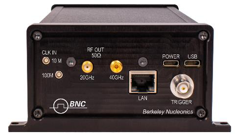
The front panel carries CLK IN (labeled 10 M and 100 M), RF OUT 50 Ω (labeled 20 GHz and 40 GHz on the RFS-1420), POWER, USB, LAN, and TRIGGER. The reference can be locked to an external 10 MHz source. RF connector types are not specified in the datasheet. (verify)
10Options & Configurations
The series ships in two factory configurations, the RFS-1220 (22 GHz) and the RFS-1420 (42 GHz), distinguished by frequency coverage and reference oscillator (TCXO on the RFS-1220, OCXO on the RFS-1420).
11Applications
- Automated testing environments: suitable for integration into automated test setups
- General RF lab use: ideal for various RF laboratory applications
- Flexible LO sourcing: can be used as a local oscillator source in different configurations
- Antenna design: useful in the development and testing of antenna systems
- EMC testing: applicable in electromagnetic compatibility testing scenarios
- Production verification and testing: suitable for production line testing and verification processes
- Educational and university lab use: beneficial for educational purposes and research in academic settings
- Aerospace and defense research: applicable in aerospace and defense research projects
- 802.11n development and testing: useful in the development and testing of 802.11n wireless standards
- Ku-band satellite link testing: suitable for testing Ku-band satellite communication links
- X-band radar applications: applicable in X-band radar system development
- Ka-band development (RFS-1420 only): suitable for Ka-band technology development and testing
- Up-converting and down-converting: can be used in frequency conversion applications
- Line of sight link testing: useful in testing line-of-sight communication links
- Wireless infrastructure design: beneficial in designing wireless communication infrastructures
- Transponder verification: suitable for verifying transponder functionalities
- 5G testing: applicable in the development and testing of 5G technology
- mm-wave technology (RFS-1420 only): suitable for millimeter-wave technology applications
12Ordering
Specify the model by frequency coverage. To request a configuration or a quote, contact Berkeley Nucleonics.
| Model | Coverage |
|---|---|
| RFS-1220 | 0.1 to 22 GHz RF and microwave signal generator |
| RFS-1420 | 0.1 to 42 GHz RF and microwave signal generator |
Berkeley Nucleonics Corporation · info@berkeleynucleonics.com · 800-234-7858