1Overview
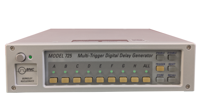
The Model 725 coordinates, integrates, and synchronizes complicated setups, simply, reliably, and affordably. Featuring eight timing channels with programmable logic, unique timing modes, and 10 ns resolution, the Model 725 outperforms a rack full of instruments, specialized boxes, filters, and cables. Inputs can be logic signals, switches, transducers, interlocks, computer commands, and gauges.
The 725 carries eight inputs, eight outputs, and eight separate timers. Each timer triggers independently, and the timers can be combined through logical operations: AND, OR, XOR, and negated forms. That logic layer is what separates the 725 from a conventional delay generator. It is engineered for fast data throughput, 11 ns typical, with minimal spread of less than 1 ns, and it includes sophisticated logic, gating, and filtering. With a single Model 725 you can synchronize cameras, lasers, shutters, choppers, solenoids, igniters, and similar devices, and even employ safety interlocks and switches. The instrument runs stand-alone or under computer control through timerPRO or LabVIEW software, and its firmware is field-upgradeable for access to new timing modes as they become available.
Delay generators have been available for years. They use a single trigger with a common clock to synchronize multiple events and cannot be retriggered until the longest timed event completes. The Model 725 instead uses eight triggers, eight timers, and eight outputs, each timer triggering independently of the others. The triggers can be logical combinations of inputs and outputs. Any number of timers can also be triggered together to function as a traditional multi-channel digital delay generator.
2Key Features
- Eight timing channels with programmable logic
- Eight independent timers, each with its own timing mode
- 10 ns delay resolution
- Eight inputs and eight outputs
- Fast data throughput, 11 ns typical
- Minimal throughput spread, about 1 ns
- Stand-alone or PC-controlled operation
- Up to 64 storable complete settings
- Sophisticated logic, gating, and filtering
- Field-upgradeable firmware
Eight timers, selectable modes for each
Each of the eight logic channels can operate independently as a clock, delayed trigger, counter, and more, all with 10 ns resolution and programmable trigger logic. You may use the internal clock or your own external clock, and you may select the timebase each channel uses, external or internal. The eight digital timing processors may be independently programmed to operate in any of the following modes:
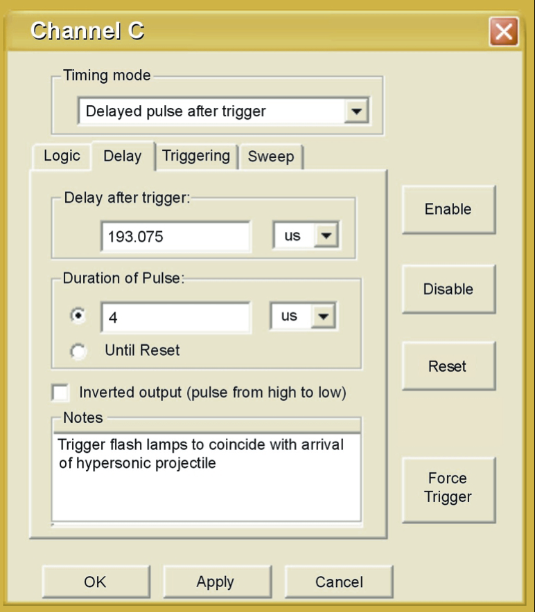
- Delayed-Pulse Mode: a pulse of specified duration after a specified delay.
- Dynamically Delayed Pulse Mode: the processor measures the delay between successive inputs, calculates an output pulse delay, then supplies an output pulse after the calculated delay, with < 20 ns uncertainty. This lets you capture elusive phenomena, such as synchronizing a flash lamp to a passing projectile or timing the spark in a cyclic combustion system.
- Toggled Output Mode: the channel toggles output with each trigger signal.
- Noise-Suppression Mode: the processor supplies an output pulse only after its input has remained high for a definable duration, guarding against false triggers from noise glitches.
- Fixed Mode: output is either high or low, regardless of input.
- Passive Mode: output equals its input, or the inverse of its input.
- Clock Mode: a repetitive pulse train with specified high- and low-state durations up to a frequency of 780 kHz.
- Timer (TDC) Mode: the processor measures, reports, and stores the delay between successive inputs, with < 20 ns uncertainty.
A channel can also be triggered N times then stop, or it may skip N triggers before providing outputs. A sweep mode increments the delay with each trigger.
3Trigger Logic & I/O
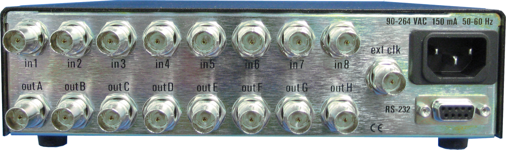
The heart of the 725 is its logic engine. Eight external inputs and seven internal logic inputs feed eight internal logic outputs that drive the timing processors. Each timing processor operates in its own mode, and logic statements (OR, AND, XOR, negated, and similar) combine external inputs and external outputs. The rear-panel input and output jacks are the combinatorial logic inputs to the timing processors. Timers can be combined with boolean operations to express conditions like fire output 3 only when input 1 and input 2 both arrive, or when input 4 arrives but input 5 does not.
Logic resources
| Resource | Detail |
|---|---|
| Timers | 8 independent, each with a unique timing mode |
| Logic operations | AND, OR, XOR, negated |
| Logic inputs | 8 external, 7 internal |
| Logic outputs | 8 internal, to the timing processors |
| Inputs / outputs | 8 in / 8 out |
| Throughput delay | 11 ns typical, ~1 ns spread |
Input and output electrical behavior
| Parameter | Value |
|---|---|
| Input impedance | 4.7 kΩ DC |
| Input capacitance | 20 pF |
| Output voltage, logic high | 3.5 to 4.9 V (typ 4.5 V into 1 kΩ load, TTL-compatible) |
| Output voltage, logic low | 0.0 to 0.2 V (typ 0.1 V) |
| Output source current, logic high | 32 to 50 mA (typ short-circuit) |
| Output source current, logic low | 64 to 80 mA (typ short-circuit) |
| Output rise time | 10 ns (1 kΩ load) |
| I/O voltage protection | −30 V to +30 V |
4Specifications
| Property | Value | Notes |
|---|---|---|
| Number of inputs/outputs | 8 in / 8 out | |
| Trigger-pulse delay (min/max) | 20 ns / 1370 s | delays over 20 s have 640 ns timing resolution |
| Trigger-pulse duration (min/max) | 7.7 µs / 1370 s | durations over 20 s have 640 ns timing resolution |
| Delay resolution | 10 ns | |
| Duration resolution | 10 ns | |
| Internal timing (min/max) | 1.5625 MHz / 100 MHz | |
| External timing (min/max) | 1 MHz / 100 MHz | |
| External trigger pulse duration (min) | 50 ns | |
| Repetition rate (min/max) | 104 µs (9.615 Hz) / 1.28 µs (781.250 kHz) | |
| Throughput delay (typ/max) | 10 ns / 11 ns | throughput spread < 1 ns |
| Delay jitter from internal source (typ/max) | 50 ps / 200 ps | |
| Delay jitter from asynchronous source (max) | 10 ns | |
| Absolute timing accuracy (typ/max) | 0.001% / 0.01% | 0 to 50°C |
| Memory storage | up to 64 complete settings (stand-alone mode) | |
| Input impedance | 4.7 kΩ DC | |
| Input capacitance | 20 pF | |
| Output voltage, logic high (min/max/typ) | 3.5 V / 4.9 V / 4.5 V | TTL-compatible, 1 kΩ load |
| Output voltage, logic low (min/max/typ) | 0.0 V / 0.2 V / 0.1 V | |
| Output source/sink current, logic high (min/typ) | 32 mA / 50 mA | short-circuit current |
| Output source/sink current, logic low (min/typ) | 64 mA / 80 mA | short-circuit current |
| Output rise time (typ) | 10 ns | 1 kΩ load |
| Input/output voltage protection | −30 V to +30 V | |
| Logic inputs | 8 external and 7 internal | |
| Logic outputs | 8 internal (to timing processors) | |
| Power requirements | 100 to 250 VAC, 50 to 60 Hz, 0.5 A min | internally fused DC supply; cooling fan; external male AC connector with fuse. Rear-panel marking: 90–264 VAC, 150 mA |
| Communication | RS-232, 38400 baud, 1 stop bit, no parity, RTS/CTS hardware flow control, 9-pin D connector | |
| Host PC & software | PC-compatible, Windows; timerPRO (included); LabVIEW drivers available | |
| Certification | CE | |
| Dimensions (W × L × H) | 208 × 242 × 60 mm (8.2″ × 9.5″ × 2.4″) | |
| Enclosure | black enamel-coated anti-RFI steel, electrostatically shielded |
5Triggering & I/O
The 725 triggers from internal or external timing. Internal timing covers 1.5625 MHz to 100 MHz, while external timing accepts 1 MHz to 100 MHz. An external trigger needs a pulse of at least 50 ns. Trigger-pulse delay spans 20 ns to 1370 s, and duration runs from 7.7 µs to 1370 s. Delays and durations over 20 s carry 640 ns timing resolution. The repetition rate ranges from 104 µs (9.615 Hz) to 1.28 µs (781.250 kHz).
Delay jitter from an internal source is 50 ps typical and 200 ps maximum. Jitter from an asynchronous source is 10 ns maximum. Absolute timing accuracy is 0.001% typical and 0.01% maximum across the 0 to 50°C range. Communication is over RS-232 at 38400 baud through a 9-pin D connector, and the instrument is controlled by the included timerPRO software or available LabVIEW drivers.
| Parameter | Value |
|---|---|
| Internal timing range | 1.5625 MHz to 100 MHz |
| External timing range | 1 MHz to 100 MHz |
| External trigger pulse duration (min) | 50 ns |
| Trigger-pulse delay | 20 ns to 1370 s |
| Trigger-pulse duration | 7.7 µs to 1370 s |
| Repetition rate | 104 µs (9.615 Hz) to 1.28 µs (781.250 kHz) |
| Communication | RS-232, 38400 baud, 9-pin D connector |
6Software & Control
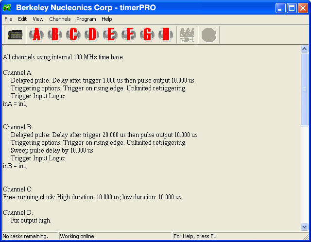
The Model 725 hardware controller operates stand-alone or under computer control. The computer control system uses its own user-friendly software, timerPRO, or LabVIEW, both tested and proven in many experiments. timerPRO makes it easy to create sophisticated control schemes from your PC, and you can set all logic using C-style syntax for quick composition. Onboard diagnostics and debugging, plus extensive Help files, tutorials, and sample files, help you get started quickly. LabVIEW drivers are available for easy integration with other lab equipment.
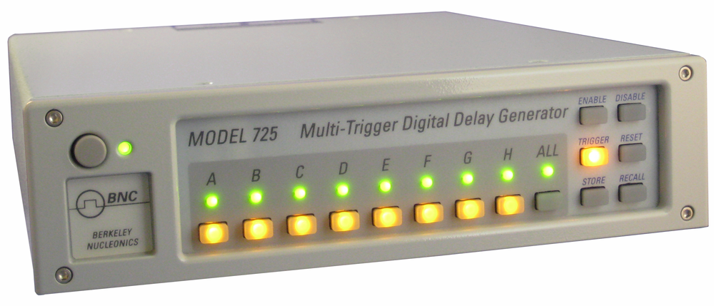
Using stand-alone mode, you can store and recall up to 64 complete settings, then trigger and monitor an experiment from the front panel. You can design experiments offline, then embed the controller in your test environment for set-and-forget operation. The firmware is field-upgradeable, so new timing modes and capabilities can be added without returning the unit.
Each channel exposes functions including enable or disable of inputs and outputs, skip N triggers before the channel triggers, retrigger N times then stop, alert the computer upon cycle completion, and sweep to select the delay increment with each trigger.
Programming and software requirements
- Standard RS-232 interface (for example, an external IBM PC-compatible COM port)
- 38400 baud, 1 stop bit, no parity, RTS/CTS hardware flow control
- Unit is supplied with a cable for a 9-pin D connector
- PC-compatible computer; trigger software for Windows 95, NT, Me, 2000, XP or later, included
- LabVIEW drivers available; other environments, call for details
7Applications
- Ballistics
- Multi-trigger input experiments
- Explosive testing
- Airbag (squib) testing
- Fluid dynamics
- High-speed gas flow
- Combustion-driven shock tubes
- Two-pulse laser experiments
- Pressure sensing and detonation control
These applications share a common need: several events arrive on independent inputs, and the system must combine them logically before acting. The 725 handles that decision in hardware, with throughput measured in nanoseconds.
Fluid dynamics
In a two-pulse experiment, two lasers were fired in rapid succession to illuminate and capture successive snapshots of a high-speed fluid flow. The Model 725 handled all aspects of the experiment, from warming up the lasers to precisely timing the nanosecond-scale pulses. Using the onboard logic, the experimenters implemented special alignment and calibration modes for preparing the experiment, plus laser-ready interlocks for safety.
High-speed gas flow
A combustion-driven shock tube was used to study high-speed gas flows. The Model 725 was the heart of the experiment, taking charge of ignition, pressure sensing, detonation, laser timing, data acquisition, and more. Inputs included control-panel switches, pressure transducers, accelerometers, ionization gauges, a safety interlock, and computer commands. Outputs drove a shutter, camera, laser flashlamp, laser Q-switch, data acquisition, oscilloscope, diaphragm burster, and igniter.
8Ordering
The Model 725 is a multi-trigger digital delay generator with eight timers, eight inputs, eight outputs, and programmable boolean logic. timerPRO software is included.
| Item | Description |
|---|---|
| Model 725 | Multi-trigger digital delay generator, 8 timers, 8 in / 8 out, programmable logic, timerPRO included |
To request a quote or discuss a multi-input synchronization setup, contact Berkeley Nucleonics Corporation at info@berkeleynucleonics.com or 800-234-7858.