1Overview
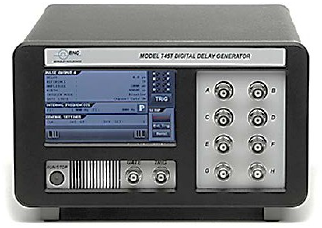
The Model 745T generator, powered by Greenfield Technology, provides four independent delay channels (A to D) on the front panel. The delay resolution is 1 ps, and the external trigger-to-channel jitter is less than 25 ps. BNC output connectors deliver 5 V, 1 ns rise-time into 50 Ω. Amplitude and width are adjustable for each output pulse.
A T0 output pulse, marking the zero delay reference, is generated at each selected trigger. Trigger sources include a RUN/STOP button, one input trigger (TRIG IN), two internal Timers, or software commands, and may be used to trigger individual output channels or all output channels.
The Model 745T also provides, as an option, four auxiliary delay channels E to H on the front panel. The delay resolution is 1.25 ns and the trigger-to-channel jitter is less than 50 ps.
All parameters (delay, pulse amplitude, width, and trigger source) may be locally controlled over the touch panel or remotely controlled over the Ethernet and Internet interface through the internal webserver.
2Features & Applications
Features
- Four high-resolution delay channels. 1 ps resolution, <5 ps RMS jitter (at short delay), 20-second delay range.
- Output pulse 5 V, 1 ns rise-time into 50 Ω, adjustable in amplitude and width.
- Trigger rates. Burst, Gate, External trigger prescaler, Internal frequency generators.
- External clock. 10 MHz or 100 MHz.
- Compact packaging.
- Full control. All parameters may be controlled via the front panel, Ethernet or Internet, or USB.
- Option. Four auxiliary delay channels.
Applications
- Component Testing
- ATE Applications
- Laser Timing Control
- Laser Pulse Picking
- Precision Pulse
- Instrument Triggering
- Embedded OEM application (in option)
3Specifications
Delay channels A to D
| Parameter | Specification |
|---|---|
| Number | 4 independents (or 8 in option) |
| Range | 0 to > 20 seconds |
| Resolution | 1 ps |
| RMS jitter | 25 ps + delay x 10⁻⁸ (external trigger to any output) 5 ps + delay x 10⁻⁸ (internal trigger to any output) |
| Accuracy | < 250 ps + delay x 10⁻⁸ |
| Timebase | 0.05 ppm stability |
External Trigger Mode
| Parameter | Specification |
|---|---|
| Input “TRIG” | Threshold = 0.1 to 5 V into 50 Ω, Slope = positive or negative |
| Repetition rate | Single, Repetitive < 1 MHz, or Burst mode |
| Trigger prescaler | 1 to 2¹⁶-1 |
| Trigger delay | < 65 ns (insertion delay) |
Internal Trigger Mode
| Parameter | Specification |
|---|---|
| Rate repetitive | From two Timers with frequency = 0.25 Hz to 1 MHz (in steps of 5 ns) |
Channel Output pulse A to D
| Parameter | Specification |
|---|---|
| Amplitude | 2 V to 5 V in steps of 10 mV |
| Load | 50 Ω |
| Rise/Fall Time | < 1 ns / < 3 ns |
| Width | 100 ns to 10 µs, 5 ns resolution |
| Pulse Polarity | Positive |
| Burst Mode | From 1 to 2¹⁶-1 |
| Connector | BNC on the front panel |
Clock IN
| Parameter | Specification |
|---|---|
| Threshold | 0 V, internal 50 Ω |
| Level | Min -3 dBm |
| Frequency | 10 MHz (up to 100 MHz as an option) |
Clock OUT
| Parameter | Specification |
|---|---|
| Frequency | 10 or 100 MHz |
| Level | +/-1 V into 50 Ω |
| Shape | Square |
Gate
| Parameter | Specification |
|---|---|
| Input | Active high, threshold 1.5 V, positive or negative slope |
| Function | Output inhibit (Global or individual channel) |
T0 output
| Parameter | Specification |
|---|---|
| Amplitude | 5 V / 50 Ω, 200 ns width |
| Connector | BNC on the rear panel |
General
| Parameter | Specification |
|---|---|
| Interface Control | Front panel, USB to UART, Ethernet 10/100Mb/s |
| User memory | Up to 4 sets of parameters can be stored/recalled via the front panel, Ethernet, or USB |
| Software tools | Free Drivers for Windows 7/10 |
| Power Supply | 90 to 240 VAC, 50 W |
| Weight | <1 kg |
| Size | 215 x 245 x 135 mm |
Option 8C: Auxiliary channels (E to H)
| Delay channel | Channel output pulse |
|---|---|
| Number: 4 independents | Amplitude: 2.5 to 5 V / 50 Ω, common tuning |
| Range: 0 to > 20 seconds | Width: 100 ns to 10 ms, 5 ns resolution |
| Resolution: 1.25 ns | Rise and fall time: <5 ns |
| Jitter: <50 ps RMS + delay x 10⁻⁸ (external trigger to any output) | Connector: BNC on the front panel |
| Accuracy: 1 ns + delay x 10⁻⁸ |
Option CLK IN & out: Clock frequency
| Parameter | Specification |
|---|---|
| Clock In or Output | Up to 100 MHz clock Input or Output (request when ordering from factory) |
4Functional Overview
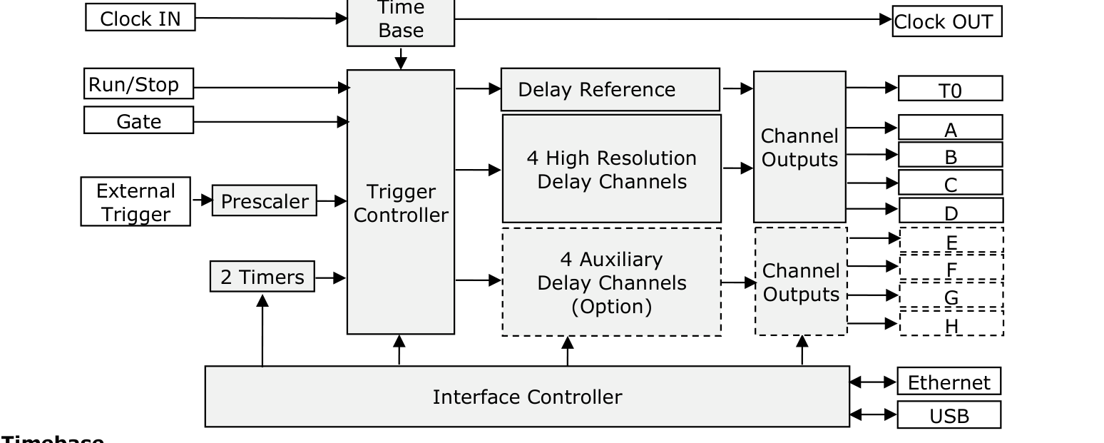
Timebase
The timebase is provided from an internal clock reference or an external 10 MHz clock (CLK IN). As an option, the external clock can be up to 100 MHz. The time base is available on the rear panel (CLOCK OUT).
Delay channel
There are four independent delay channels. The delay from the selected trigger source is adjustable up to 20 seconds in 1 ps increments.
Jitter: The following indicates typical RMS jitter at various delays:
| Internal Trigger Mode | External Trigger Mode |
|---|---|
| Delays < 100 ns: 5 ps | Delays < 100 ns: 5 ps |
| Delays > 100 ns: 15 ps + delay x 10⁻⁸ | Delays > 100 ns: 25 ps + delay x 10⁻⁸ |
Triggering
The Model 745T offers users several methods for triggering delay channels:
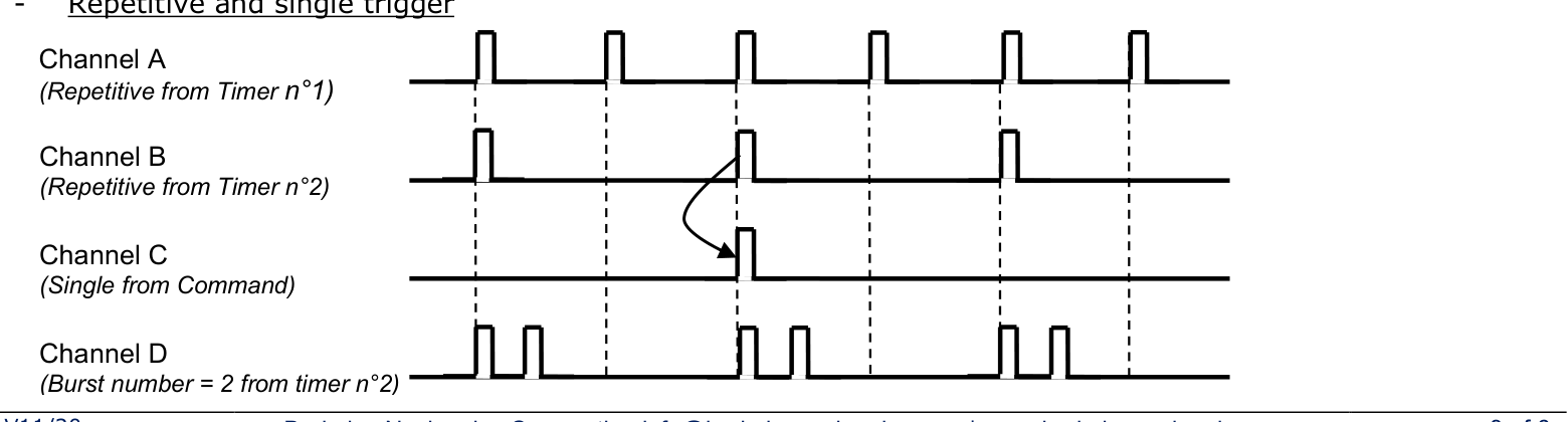
- Externally trigger on the positive or negative slope of your trigger signal and selected level from 0.1 to 5.0 V.
- Two frequency programmable Timers are adjustable from 0.25 Hz to 1 MHz in 1 Hz increments (5 ns).
- Software trigger from remote command.
Trigger Modes
- Burst mode: pulse number 1 to 2¹⁶-1, period 1000 ns to 1 second (depending on the trigger rate).
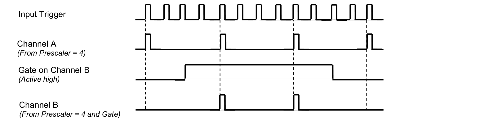
- Trigger Pre-scaler: pre-scaler value applied to the external trigger goes from 1 to 2¹⁶-1.
- Gate mode: can be set to global or individual channel.
Outputs
On the front panel, each delay channel output pulse is independently adjustable in level and width. The outputs are designed to drive an external 50 Ω load. T0 Output pulse is a time reference that marks zero delay.
Interface Control
All parameters may be locally controlled via touch screen or remotely controlled via Ethernet or USB. The Model 745T has an embedded control interface software that allows all parameters to be controlled by any PC with a browser.
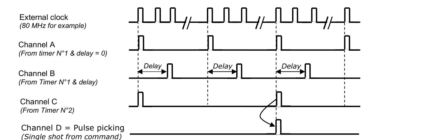
5Trigger Modes & Examples
Repetitive and single trigger
Prescaler and gate mode
Pulse picking
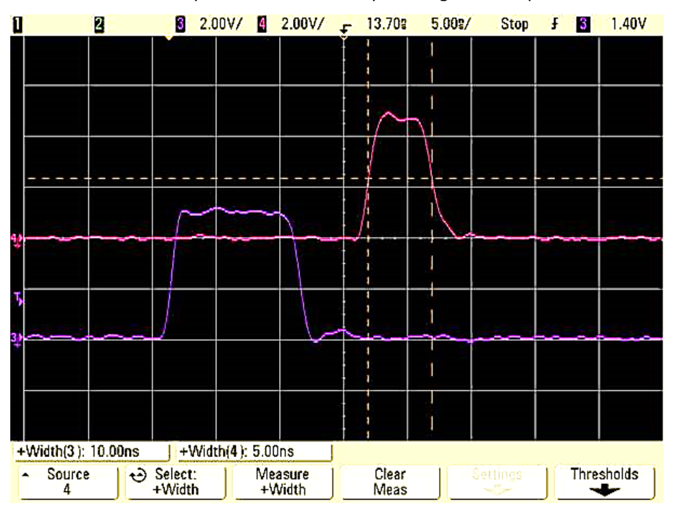
6Narrow Pulse Option
The narrow pulse option provides pulses up to 5 ns width, on the outputs T1 and T3. The value of width is adjustable in steps of 1 picosecond. The narrow pulse is achieved by mixing two outputs.
7Control & Software Tools
There are three ways to control the generator.
“Local way” via the touch screen
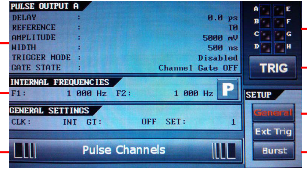
A three-level Menu is available:
- A main menu displays settings.
- Sub-Menus to select the parameter to set.
- Keyboard to set the new parameter value.
“Easy remote way” via Internet and control panel web pages
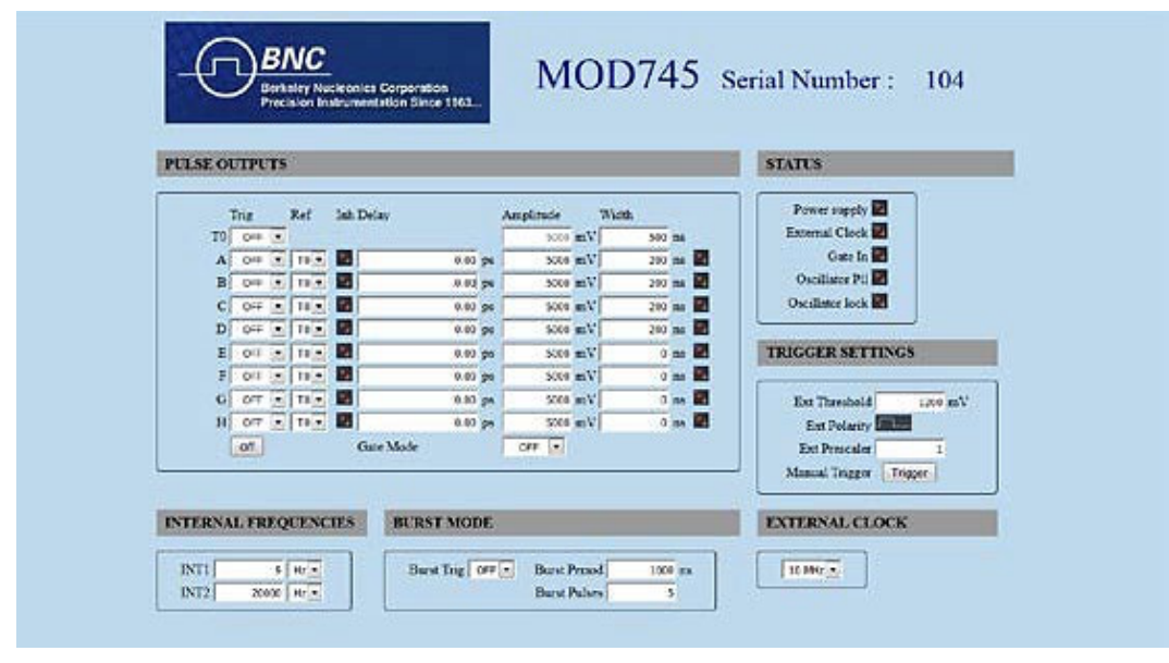
A web page, from an embedded Web server, provides a simple method to configure settings for each channel (delay, output amplitude, polarity, output width, trigger mode, trigger source), to control operation, and to display the status of the instrument.
The configuration information of the instrument is stored and saved in the Model 745T. The web page can be opened via Internet Explorer, Mozilla Firefox, or Google Chrome.
After connecting a cable from the Model 745T's Ethernet port to your computer network, enter the Model 745T's IP address into your PC's browser (the IP address can be identified or assigned via the front panel). The browser will automatically open the control panel web page on your PC.
“General remote way” via BNC software application or other PC software applications
The Model 745T can also be controlled by the BNC software application or by other PC software applications.
8Input / Output Interface
Front and Rear Panel
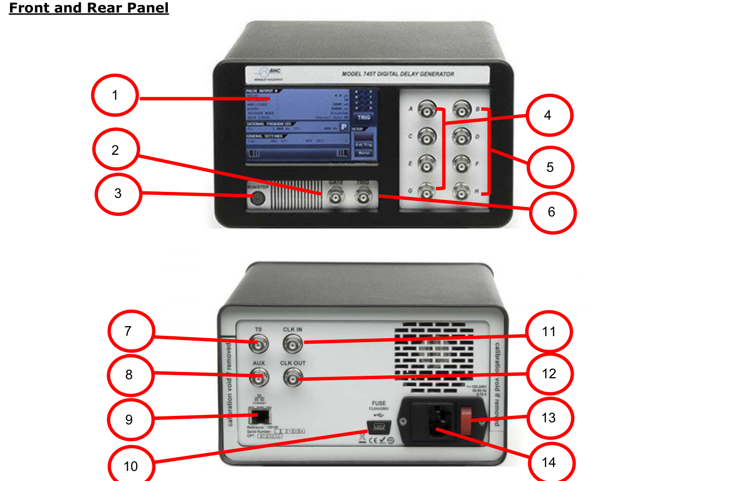
| Front Panel | Rear Panel |
|---|---|
| 1 Touch screen for local control | 7 T0 output, BNC connector |
| 2 GATE input, BNC connector | 8 AUX, No function |
| 3 RUN/STOP for single-shot triggers | 9 (Ethernet), RJ45 connector |
| 4 A, B, C, D pulse outputs, BNC connector | 10 (USB interface), micro-USB connector |
| 5 E, F, G, H auxiliary outputs, BNC connector | 11 Clock INput, BNC connector |
| 6 TRIG input: BNC connector | 12 Clock OUTput, BNC connector |
| 13 POWER ON/OFF switch | |
| 14 AC power plug (90-240 V) |
9Ordering & Accessories
Ordering Information
| Model | Description |
|---|---|
| Model 745T-4C | Base version: 4 high-resolution delay channels |
| Model 745T-8C | Adds 4 auxiliary channels |
| Model 745T-XC-CLK | Up to 100 MHz clock Input (or Output) |
| Model 745T-NRW | Adds narrow pulse version |
| Model 745T-RM1 | 19” Rack-mount kit, Single unit |
| Model 745T-RM2 | 19” Rack-mount kit, Dual units |
| Model 745-OEM | OEM version (board level) of the Model 745T |
Accessories (pulse shaping modules)
| Model | Description |
|---|---|
| GFT101 | Electrical-to-optical, Pulse Converter |
| GFT632 | 32 - 70 V, 3 ns rise time into 50 Ω, Pulse Generator |
| GFT644 | 4 channel 50 Ω Line Driver Module |