1Overview
The 825-M is a very compact, very agile signal source spanning 100 kHz to 20 GHz, extendable to 8 kHz with Option 8K. It combines fast switching with low phase noise and good signal purity. The single-channel unit is available as a flange- and rack-mountable module or in a compact desktop enclosure with front panel control. The multi-channel version (Model 825-M-20-X) is available in 1, 2, 3 or 4 channel configurations in a standard 1U 19-inch rackmount enclosure.
On multi-channel units, all RF channels lock to a common frequency reference to achieve high phase coherence between channels. The Fast Control Port (FCP) provides ultra-fast user-controlled list sweeping and frequency hopping. All communication ports support the SCPI 1999 command set.
2Key Features
- Low phase noise
- Fast switching down to 5 µs
- Chirps and pulse modulation
- Internal OCXO with external variable reference
- Up to four phase-coherent channels locked to one reference
3Frequency & Output Power
The standard frequency range is 100 kHz to 20 GHz, extended down to 8 kHz with Option 8K. Frequency resolution is 0.01 Hz and phase resolution is 0.1 deg. The internal reference holds ±40 ppb initial accuracy (calibrated at 23 ± 3 °C) and ±100 ppb temperature stability from 0 to 50 °C.
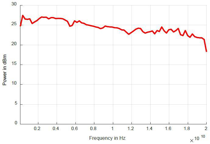
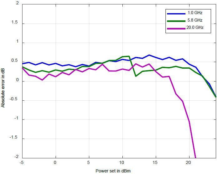
Typical output power range is 0 to +18 dBm, settable from -10 to +23 dBm, with 0.5 dB resolution. Level uncertainty is ±1.5 dB. Configurations range from a single channel to four channels in a 1U rackmount.
Output impedance is 50 Ω with a typical VSWR of 1.7 (2.0 maximum). The output is protected against reverse power up to 7 V DC and 23 dBm RF.
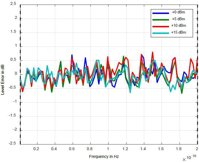
Level accuracy holds within approximately ±1 dB across the band at common output levels.
4Phase Noise & Spectral Purity
Phase Noise
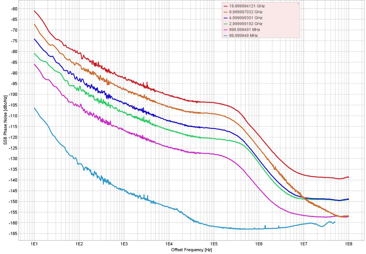
SSB phase noise is specified at a 1 GHz carrier. See also the measured plots across carriers from 100 MHz to 20 GHz.
| Parameter | Typical |
|---|---|
| At 10 Hz from carrier | -85 dBc/Hz |
| At 1 kHz from carrier | -115 dBc/Hz |
| At 20 kHz from carrier | -125 dBc/Hz |
| At 10 MHz from carrier | -155 dBc/Hz |
Spectral Purity
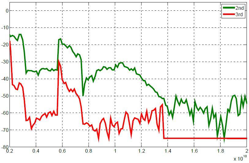
Output harmonics, sub-harmonics and non-harmonic spurious are specified at Pout = 0 dBm.
| Parameter | Typical | Max | Note |
|---|---|---|---|
| Output harmonics, < 3.0 GHz | -15 dBc | 0 dBc | Pout = 0 dBm |
| Output harmonics, 3.0 – 7.5 GHz | -25 dBc | -10 dBc | |
| Output harmonics, 7.5 – 12.0 GHz | -30 dBc | -20 dBc | |
| Output harmonics, > 12.0 GHz | -40 dBc | -30 dBc | |
| Sub-harmonics, < 10.0 GHz | -80 dBc | -50 dBc | Pout = 0 dBm |
| Sub-harmonics, 10.0 – 18.0 GHz | -55 dBc | -40 dBc | |
| Sub-harmonics, > 18.0 GHz | -40 dBc | -20 dBc | |
| Non-harmonic spurious, ≤ 18.0 GHz | -65 dBc | -50 dBc | 10 kHz < offset < 500 MHz |
| Non-harmonic spurious, > 18.0 GHz | -55 dBc | -35 dBc |
5Frequency Switching & Agility
The 825-M is the fastest-switching synthesizer in the family. Standard switching speed is 200 µs (500 µs in sweep mode). Option FS reduces switching to 5 µs, or 10 µs in sweep mode, and includes the Fast Control Port for streamed frequency and amplitude updates.
That agility, paired with up to four phase-coherent channels locked to a single reference, suits fast hopping, beam steering, and time-critical ATE sequencing. Frequency and list sweeps are supported alongside chirp generation.
6Modulation, Sweeping & Trigger
The 825-M supports pulse modulation, chirps, and frequency and list sweeps. Modulation source can be internal or external.
Pulse Modulation
| Parameter | Min | Typical | Max | Note |
|---|---|---|---|---|
| On/off ratio | 60 dB | |||
| Repetition frequency | DC | 10 MHz | ||
| Pulse width | 30 ns | 20 s | ||
| Pulse rise/fall time | 9 ns | |||
| Pulse trains length (pulses) | 2 | 4192 | ||
| Video crosstalk | -40 dB | |||
| Modulation source | Int. / ext. | |||
| External input threshold | 0.85 V | 0.9 V | 0.95 V | TTL compatible |
| External input voltage range | -0.5 V | +5.5 V | TTL compatible | |
| External input hysteresis | 60 mV | |||
| Delay (to RF) | 20 ns | 40 ns |
Sweeping Capability
Frequency and list sweeps support linear, logarithmic and random sweep types. A generalized list sweep allows individual setting of frequency, step-time and off-time for each point.
| Parameter | Min | Typical | Max | Note |
|---|---|---|---|---|
| Step time | 500 µs | 200 s | ||
| Step time (Option FS) | 5 µs | Option FS | ||
| Timing resolution | 5 ns | |||
| Timing accuracy per point | 20 ns |
Trigger
| Parameter | Min | Typical | Max | Note |
|---|---|---|---|---|
| Trigger types | Continuous, single (point), gated, gated direction | |||
| Trigger source | External, bus (LAN, USB) | |||
| Trigger modes | Continuous free run, trigger and run, reset and run | |||
| Trigger uncertainty | 5 µs | |||
| External trigger delay | 50 µs | 40 s | ||
| External delay resolution | 15 ns | |||
| Trigger modulo | 1 | 255 | Execute only on Nth trigger event | |
| Trigger polarity | Rising, falling | |||
| External trigger input threshold | 0.85 V | 0.9 V | 0.95 V | TTL compatible |
| External trigger input voltage range | -0.5 V | +5.5 V | TTL compatible | |
| External trigger input hysteresis | 60 mV | |||
TRIG OUT connector is not available in the standard flange-mount enclosure.
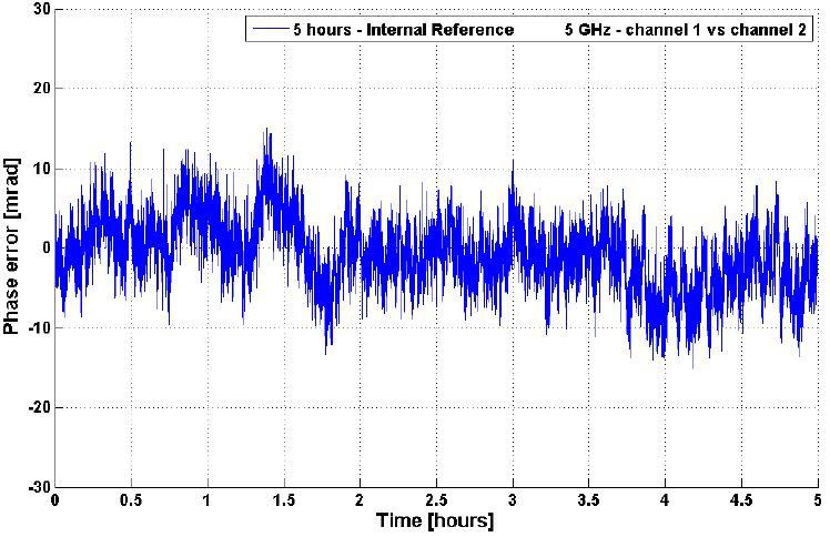
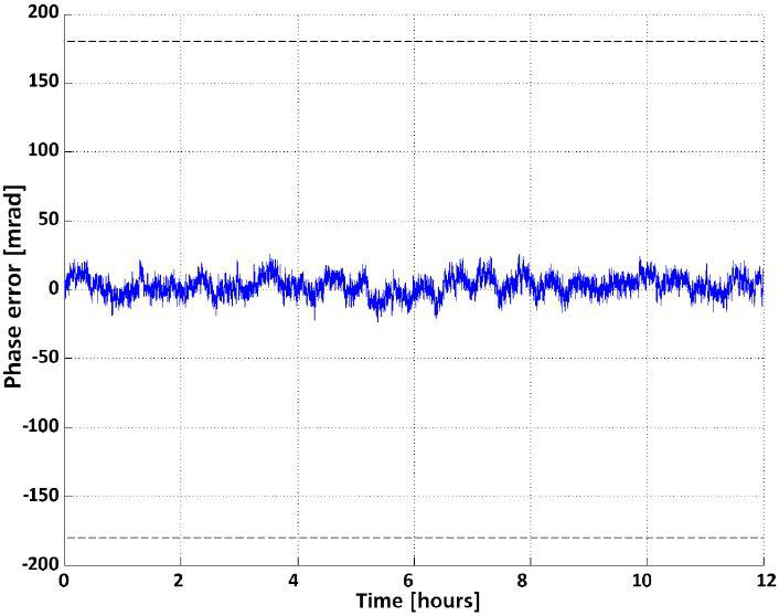
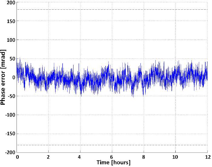
Channel-to-Channel Performance
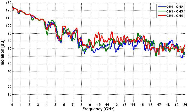
On multi-channel units, RF channels lock to a common frequency reference for high phase coherence. Isolation is 90 dB below 3.0 GHz, 70 dB from 3.0 to 8.0 GHz, and 60 dB typical above 8.0 GHz. Relative phase stability is 15 mrad at 5 GHz over 5 hours.
Analog AM, FM and PM modulation are not listed in datasheet v132; confirm analog modulation support with the factory. (verify)
7Specifications
| Parameter | Specification |
|---|---|
| Number of channels | 1, 2, 3, or 4 |
| Frequency range | 100 kHz to 20 GHz (8 kHz to 20 GHz with Option 8K) |
| Frequency resolution | 0.01 Hz |
| Phase resolution | 0.1 deg |
| Reference accuracy | ±40 ppb initial (23 ± 3 °C); ±100 ppb over 0 to 50 °C; lock range ±1.0 ppm |
| Output power | 0 to +18 dBm typical; settable -10 to +23 dBm; 0.5 dB resolution |
| Level uncertainty | ±1.5 dB |
| Output impedance / VSWR | 50 Ω; VSWR 1.7 typical (2.0 max) |
| Reverse power protection | 7 V DC; 23 dBm RF |
| Switching speed | 200 µs (5 µs with Option FS); 500 µs in sweep mode (10 µs with Option FS) |
| Modulation | Pulse; chirps |
| Sweeps | Frequency, list (linear, logarithmic, random); generalized list sweep |
| Remote control | Ethernet, USB 2.0, GPIB (optional); SCPI v1999.0; Fast Control Port (FCP) |
| Reference | Internal 100 MHz OCXO; external variable reference 1 to 200 MHz (integer MHz) |
| Power requirements | 24 VDC; 20 W maximum (mains adapter 100–240 VAC in / 24 V, 2 A DC out) |
| Operating temperature | 0 to 45 °C |
| Storage temperature | -40 to 70 °C |
| Operating / storage altitude | Up to 15,000 feet |
| Dimensions, flange-mount (W × L × H) | 4.13 × 10.63 × 2.36 in (105 × 270 × 60 mm) |
| Dimensions, 1U rackmount (W × L × H) | 16.85 × 18.39 × 1.73 in (428 × 467 × 44 mm) |
| Weight | ~2 lbs (≤1.0 kg) flange-mount; ~21 lbs (≤10.0 kg) 1U rackmount |
| Recommended calibration cycle | 24 months |
| Safety / EMC | Complies with applicable Safety and EMC regulations and directives |
8Interfaces & Form Factor
Control is over Ethernet and USB 2.0, with optional GPIB, using SCPI v1999.0. The reference is an internal 100 MHz OCXO with support for an external variable reference from 1 to 200 MHz. The 1U rackmount enclosure measures 16.85 by 18.39 by 1.73 inches (428 × 467 × 44 mm) and weighs about 21 lbs. The flange-mount module measures 4.13 by 10.63 by 2.36 inches (105 × 270 × 60 mm) and weighs about 2 lbs.
Single-channel units are available as a flange- and rack-mountable module or in a compact desktop enclosure with front panel control.
Fast Control Port (FCP)
The FCP is an 8-bit or 16-bit parallel port for fast, time-critical settings such as frequency. It supports sequential submission of a 48-bit frequency word or access to a pre-defined frequency table, with optional amplitude control and multi-channel support on the 16-bit bus. The signal source confirms received data with ACK (8-bit mode only) and signals processing with BUSY.
| Parameter | Specification |
|---|---|
| Connector | 26 pin 3M Mini-D Ribbon Receptacle |
| 8-bit mode | Address A<3..0>, Data D<3..0>, STROBE, ACK, BUSY |
| 16-bit mode | Address A<7..0>, Data D<7..0>, STROBE, BUSY |
| Input signal | 0 to 5 V |
| Input impedance | 4.7 kΩ |
| Maximum toggle rate | 10 MHz; frequency switching starts after transfer of last byte |
9Options & Configurations
| Option | Description |
|---|---|
| Option EB | External power bank adapter cable |
| Option 8K | Frequency range extension to 8 kHz |
| Option FS | Fast switching option (with FCP port) |
| Option HI | High Isolation Enclosure |
| Option GPIB | GPIB interface (only with 1U rack-mount option) |
| Option FLASH | MicroSD card slot for removable SD memory |
| Option Retrofit | Applies when options are back-ordered |
| Variant | Description |
|---|---|
| 825-M | 20 GHz wideband frequency synthesizer, flange-mount |
| 825-M-20 | Single-channel 20 GHz signal source, compact module or desktop enclosure |
| 825-M-20-X | Multi-channel 20 GHz frequency synthesizer, 1, 2, 3 or 4 channels, 19-inch 1U rackmount |
10Applications
- Automated test environment (ATE)
- Local oscillator for frequency converters
- Telecom / Satellite Com
11Ordering
Specify the channel count, Option FS for fastest switching, Option 8K for the extended 8 kHz low end, and any enclosure or interface options. To configure a multi-channel system or request a quote, contact Berkeley Nucleonics.
Berkeley Nucleonics Corporation · info@berkeleynucleonics.com · 800-234-7858