- Form factor. The source document specifies the SAE/NXE module hardware. It does not state handheld-specific mechanics (display size, battery life, ingress rating, drop rating). Those handheld attributes are therefore omitted rather than invented. verify.
- Model mapping. The numeric part is the maximum frequency in GHz times 10 and is preserved exactly. The three frequency variants map to ICX-090 (9 kHz to 9.5 GHz), ICX-200 (9 kHz to 20 GHz), and ICX-400 (9 kHz to 40 GHz). The ICX-400 (40 GHz) is part of the ICX-FieldHawk line; its specifications, including the 2.4 mm (M) RF input, are drawn from the 40 GHz product documentation.
- Software rename. The source control software is renamed throughout to SpecICX-gen3, Berkeley Nucleonics' spectrum analysis firmware. Described functionality is unchanged.
- Antenna accessories. External antennas are presented as accessories drawn from the ANT-100G family. Confirm the part number. verify.
- Specifications. All spec values are reproduced identically from the source for the same measurement hardware. Tables were lightly regrouped for readability. Values remain preliminary pending verification against the published BNC datasheet. verify.
- In-software branding. The SpecICX-gen3 screenshots in sections 2 and 3 carry the source vendor wordmark masked from the application title bar. Recapture with the BNC / SpecICX-gen3 mark when available. verify.
1Overview
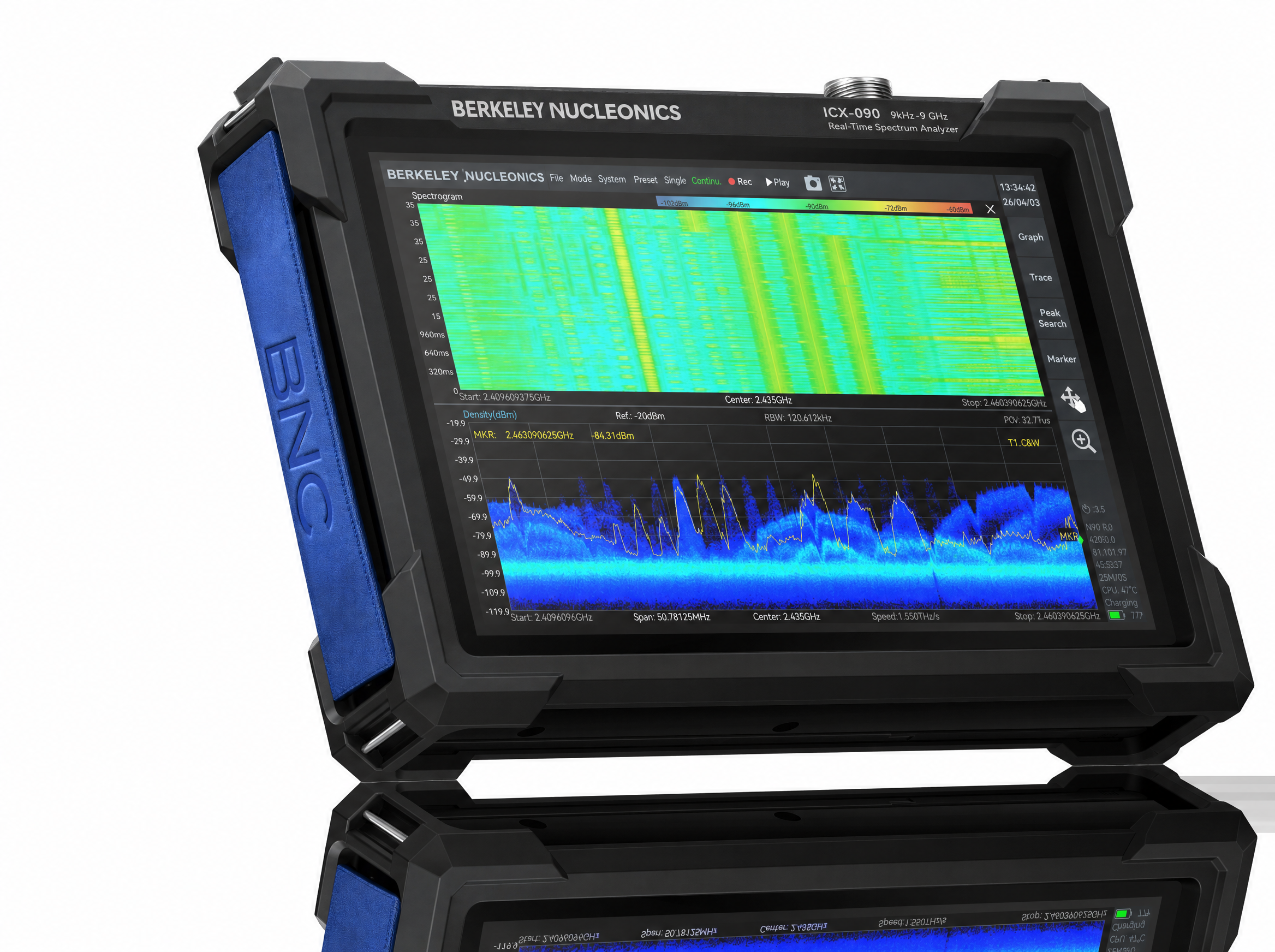
The ICX-FieldHawk Handheld is a high-performance real-time spectrum analyzer that delivers strong RF performance in a field-portable package. It holds spectral purity under demanding conditions and cuts both deployment and operating cost, which makes it well suited to space- and cost-constrained applications where a full benchtop instrument would be impractical.
Connectivity and control
The instrument pairs the FPGA acquisition core with the SpecICX-gen3 application. Beyond the measurement engine, every model shares one consistent interface, so a measurement set up on one unit transfers directly to another.
Unified API
Every model shares one consistent API. You can migrate from one unit to another without changing application code. Development is supported in C/C++, C#, Python, MATLAB, Qt, and LabVIEW, on both Windows and Linux. The instruments also speak the standard SCPI protocol.
Measurement functions
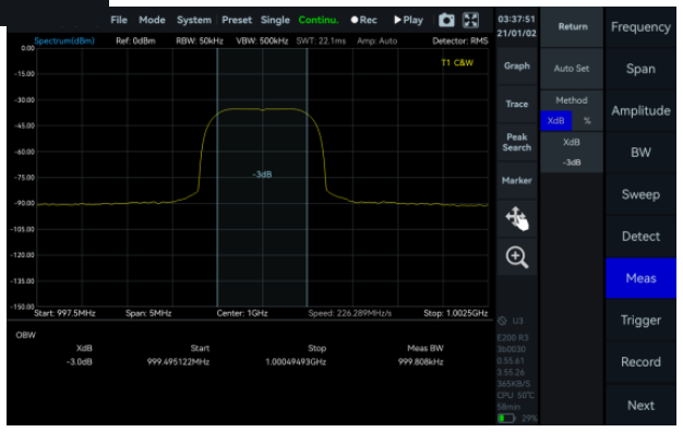
A rich set of advanced measurements ships as standard, including channel power, occupied bandwidth, X dB bandwidth, harmonic measurement, spectrum emission mask (SEM), AM and FM demodulation, and automatic phase noise analysis.
Key features
- Frequency: 9 kHz to 9.5 GHz (ICX-090), 9 kHz to 20 GHz (ICX-200), or 9 kHz to 40 GHz (ICX-400)
- 1 GHz DANL: -166 dBm/Hz
- 1 GHz phase noise: better than -100 dBc/Hz at 10 kHz offset
- Analysis bandwidth: 100 MHz
- Real-time engine: gapless, overlap-free FPGA FFT across the full bandwidth
- Unified API: highly compatible, hardware-portable API interface
- Windows support: 11 / 10 / 8 / 7 (x86, x64, AArch64)
- Debian support: 12 / 11 / 10 (x64, AArch64)
- Ubuntu support: 24.04 / 22.04 / 20.04 / 18.04 (x64, AArch64)
- Standard SCPI protocol support
2Operating Modes
SpecICX-gen3, Berkeley Nucleonics' spectrum analysis firmware, offers seven main operating modes: Standard Spectrum Analysis, IQ Streaming, Power Detection Analysis, Real-Time Spectrum Analysis, Phase Noise Measurement, Digital Demodulation (option), and Harmonics Analysis. Each mode reuses the same acquisition hardware, so switching between them takes no rewiring.
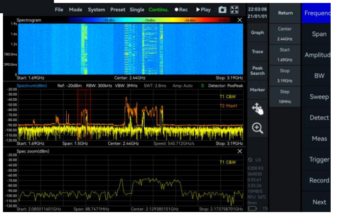
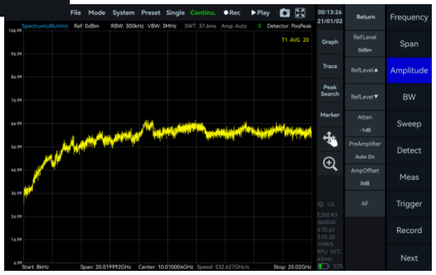
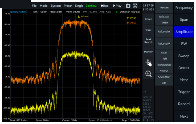
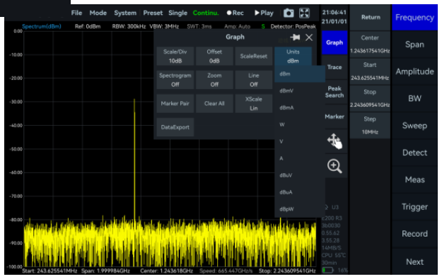
Standard Spectrum Analysis
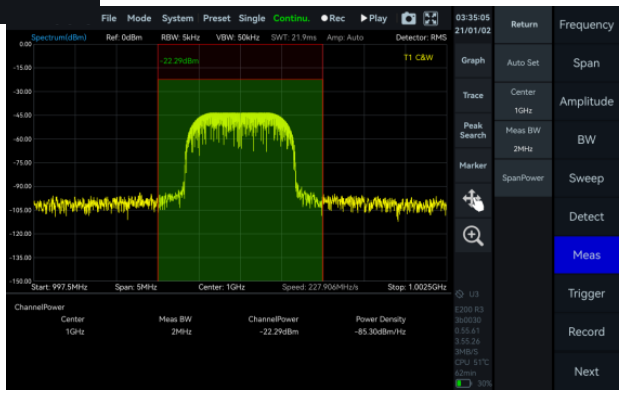
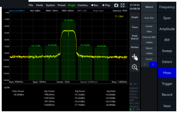
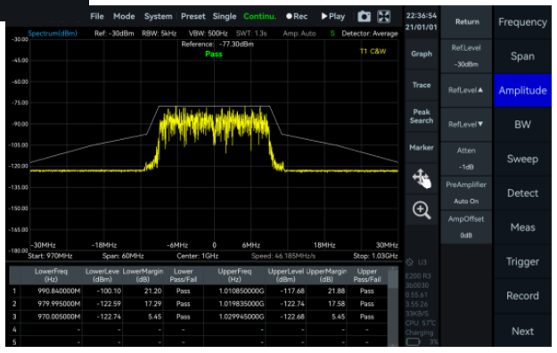
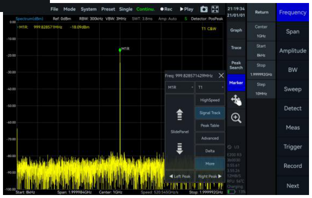
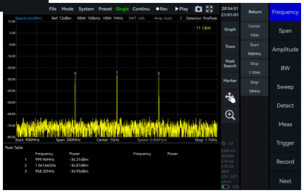
This mode provides a wide range of measurement functions, including full-span spectrum sweep, channel power, OBW, ACPR, IM3, and SEM. It also supports spectrum recording and playback. Combined with auxiliary tools such as signal tracking, the peak table, and amplitude correction, it gives you a one-stop platform for thorough spectrum inspection.
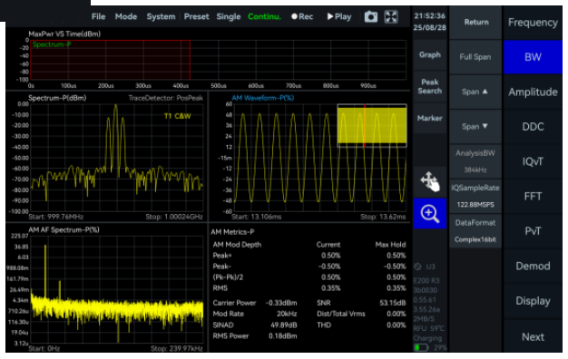
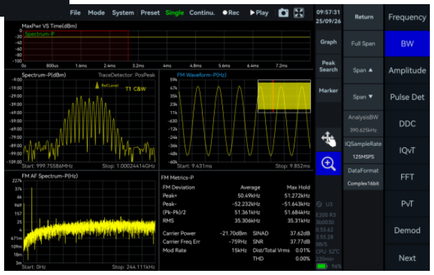
IQ Streaming
This mode supports up to 100 MHz of analysis bandwidth and acquires IQ data through multiple trigger methods. It provides IQ time-domain waveform display, spectrum and spectrogram views, AM and FM demodulation, and digital down conversion (DDC).
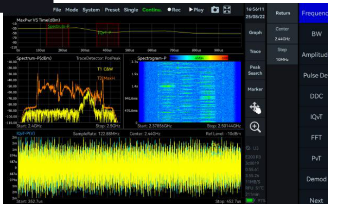
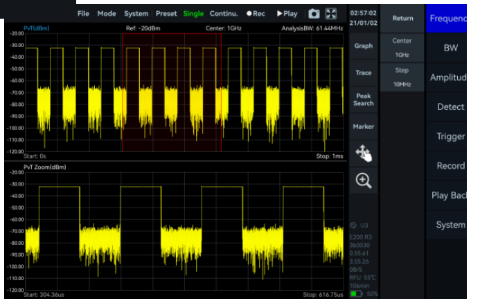
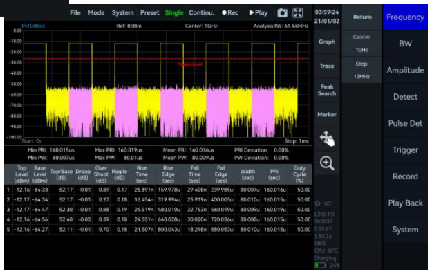
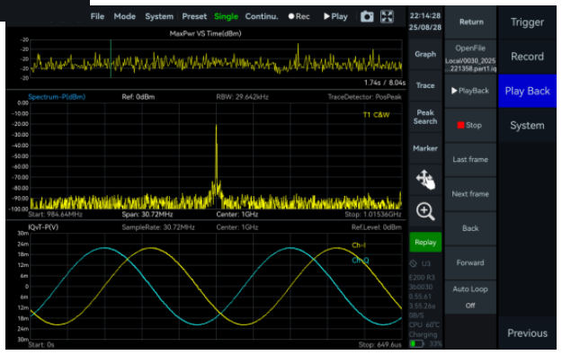
Power Detection Analysis
This mode detects and analyzes time-domain signals within the analysis bandwidth. It suits applications focused on in-band power versus time, such as pulse signal measurement.
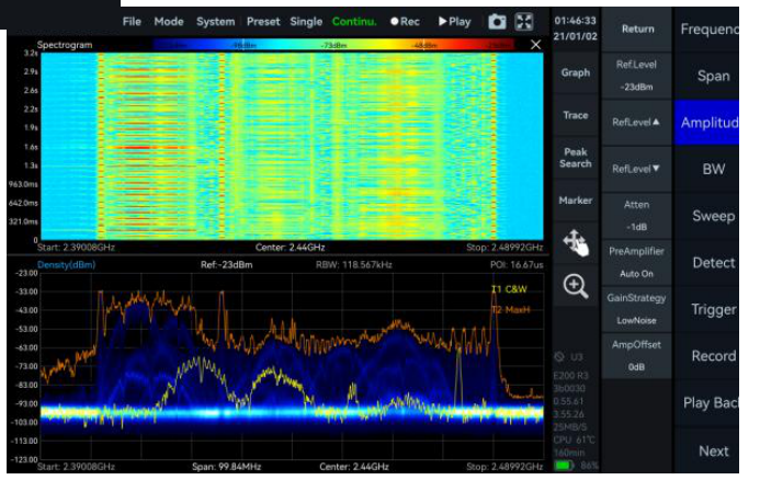
Real-Time Spectrum Analysis
This mode is powered by a high-speed, FPGA-based FFT engine. The FFT is strictly gapless and overlap-free, so the instrument achieves true real-time monitoring across the full bandwidth with no samples lost between frames.
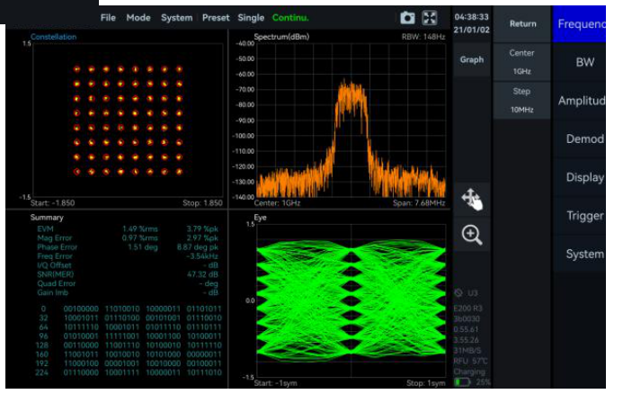
Digital Demodulation (option)
This optional mode supports 2ASK, 2FSK, 4FSK, GMSK, BPSK, QPSK, 8PSK, 16QAM, 64QAM, 128QAM, and 256QAM signals.
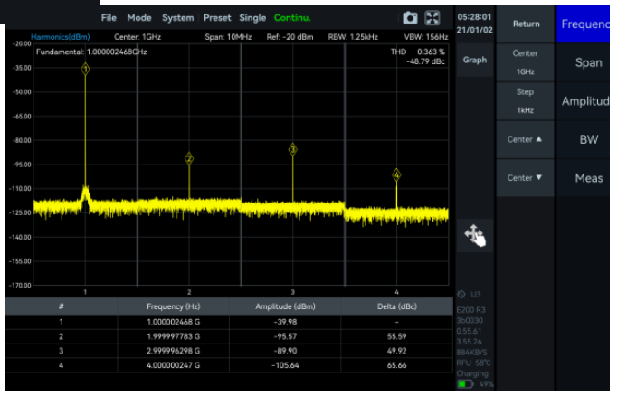
Harmonics Analysis
This mode detects and measures up to 10 harmonic components, reporting harmonic peaks, harmonic channel power, and total harmonic distortion.
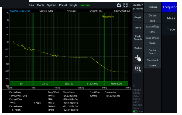
Phase Noise Measurement
This mode covers offset ranges from 1 Hz to 10 MHz for evaluating carrier phase stability. A built-in automatic carrier search quickly locates the target carrier, so no manual tuning is needed.
3Measurement Functions
The following functions are available within SpecICX-gen3. Each is illustrated with a representative measurement screenshot from the source material.
Power and channel measurements

Mask and modulation analysis
Correction and tooling
4Frequency Specifications
| Parameter | 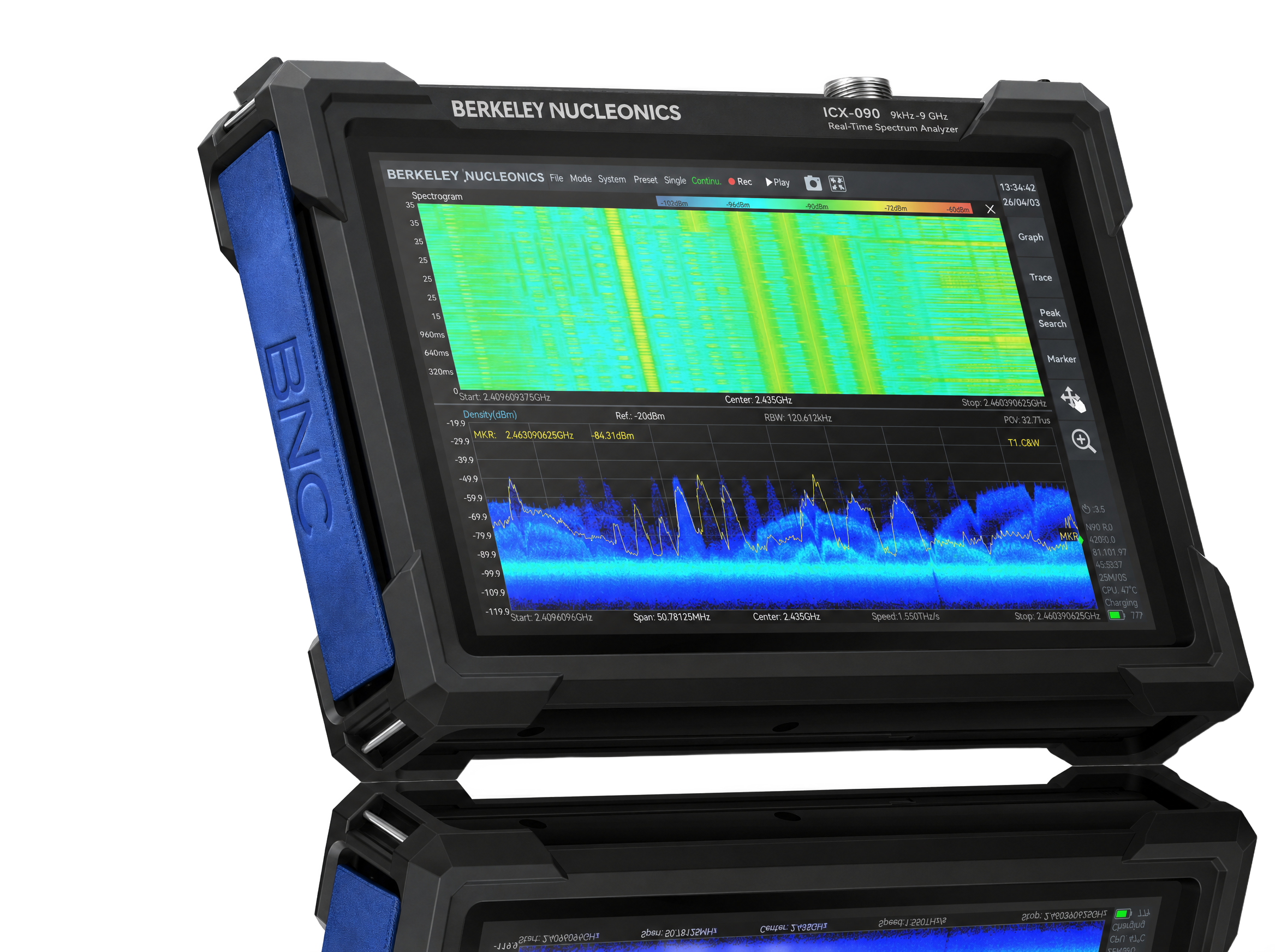 ICX-090 ICX-090 | ICX-200 | ICX-400 |
|---|---|---|---|
| Frequency range | 9 kHz to 9.5 GHz | 9 kHz to 20 GHz | 9 kHz to 40 GHz |
| Reference clock | Internal or external | ||
| Frequency accuracy, TCXO (std.) | <1 ppm, manual correction available | ||
| Frequency accuracy, OCXO (opt 01) | <1 ppm, manual correction available | ||
| Frequency accuracy, GNSS-disciplined OCXO (opt 23/06) | <0.05 ppm when locked to GNSS | ||
| Aging & temp. stability, TCXO (std.) | <1 ppm/year, <1 ppm | ||
| Aging & temp. stability, OCXO (opt 01) | <1 ppm/year, <0.15 ppm | ||
| Aging & temp. stability, GNSS-disciplined OCXO (opt 23/06) | <1 ppm/year, <0.05 ppm | ||
5Spectrum Purity
SSB phase noise (dBc/Hz)
| Offset | ICX-090 · 1 GHz | ICX-090 · 9.5 GHz | ICX-200 · 1 GHz | ICX-200 · 20 GHz | ICX-400 · 1 GHz | ICX-400 · 40 GHz |
|---|---|---|---|---|---|---|
| 1 kHz | -95.2 | -91.5 | -91.2 | -80.6 | -99.0 | -78.4 |
| 10 kHz | -101.6 | -98.5 | -99.7 | -90.6 | -107.5 | -85.7 |
| 100 kHz | -100.6 | -99.7 | -101.1 | -96.2 | -107.7 | -85.1 |
| 1 MHz | -120.9 | -116.2 | -121.6 | -111.5 | -122.7 | -100.8 |
Residual response (dBm)
Conditions: spur reject = bypass, RBW = 1 kHz, PosPeak detector.
| Frequency band | ICX-090 · R.L. 0 dBm | ICX-090 · R.L. -50 dBm | ICX-200 · R.L. 0 dBm | ICX-200 · R.L. -50 dBm | ICX-400 · R.L. 0 dBm | ICX-400 · R.L. -50 dBm |
|---|---|---|---|---|---|---|
| 9 kHz to 1 GHz | -83 | -120 | -90 | -120 | -72 | -103 |
| 1 GHz to 3 GHz | -83 | -120 | -80 | -120 | -72 | -103 |
| 3 GHz to 9.5 GHz | -90 | -130 | -90 | -120 | -72 | -103 |
| 9.5 GHz to 20 GHz | - | - | -90 | -120 | -91 | -115 |
| 20 GHz to 40 GHz | - | - | - | - | -85 | -103 |
Image rejection (dBc), typical
| Frequency band | ICX-090 · standard | ICX-090 · bypass | ICX-200 · standard | ICX-200 · bypass | ICX-400 · standard | ICX-400 · bypass |
|---|---|---|---|---|---|---|
| 90 MHz to 3 GHz | >90 | >76 | >90 | >79 | >90 | - |
| 3 GHz to 9.5 GHz | >90 | >60 | >90 | >68 | >90 | - |
| 9.5 GHz to 20 GHz | - | - | >90 | >60 | >90 | - |
| 20 GHz to 33 GHz | - | - | - | - | >90 | - |
| 33 GHz to 40 GHz | - | - | - | - | >58 | - |
IF rejection and spurious (dBc), typical
| Parameter | Spur reject enhanced | Bypass |
|---|---|---|
| IF rejection | >90 | >80 |
| IF rejection (ICX-400) | >68 (8.2 to 21.75 GHz); >90 (other bands) | - |
| Local oscillator related spurious | <-65 dBc at center frequency ± (N/M) × 125 MHz, where N, M = 1, 2, 3, 4, 5... | |
IIP3 / IIP2 (dBm)
| Reference level | ICX-090 · 1 GHz | ICX-090 · 9.5 GHz | ICX-200 · 1 GHz | ICX-200 · 20 GHz | ICX-400 · 1 GHz | ICX-400 · 40 GHz |
|---|---|---|---|---|---|---|
| R.L. = 20 dBm | 46.1 / 83.2 | 40.5 / 92.8 | 45.5 / 82.6 | 35.3 / 93.6 | 40.3 / 75.5 | 31.7 / 88.6 |
| R.L. = 0 dBm | 26.7 / 85.0 | 19.2 / 90.3 | 25.5 / 81.1 | 21.0 / 89.0 | 27.4 / 45.3 | 10.3 / 86.1 |
| R.L. = -20 dBm | 10.5 / 82.2 | 2.0 / 49.3 | 7.9 / 81.5 | -4.5 / 55.3 | 8.7 / 25.2 | 4.8 / 66.6 |
6Amplitude
| Parameter | Value | Condition |
|---|---|---|
| Max. input power (CW) | 23 dBm | 50 MHz to 9.5/20/40 GHz, preamplifier off |
| Max. input power (CW) | 10 dBm | 9 kHz to 50 MHz, or preamplifier on |
| Max. DC voltage | ±10 VDC | |
| Display range | DANL to 23 dBm | ICX-090 / ICX-200 |
| Display range | DANL to 20 dBm | ICX-400 |
| Amplitude accuracy | ±2.0 dB | 9 kHz to 9.5 GHz |
| Amplitude accuracy | ±3.0 dB | 9.5 GHz to 20/40 GHz |
| IF in-band flatness | ±2.0 dB | |
| Reference level (R.L.) | -50 dBm to +23 dBm | ICX-090 / ICX-200 |
| Reference level (R.L.) | -50 dBm to +20 dBm | ICX-400 |
| RF preamplifiers | Automatic on, or forced off | |
| VSWR | <2.0:1 | 90 MHz to max. frequency (ICX-090 / ICX-200) |
| VSWR | <2.0:1 / <3.0:1 | ICX-400: 90 MHz to 16 GHz / 16 GHz to 40 GHz |
7Display Average Noise Level (DANL)
Units: dBm/Hz. Condition: RBW = 1 kHz.
| Frequency band | ICX-090 · R.L. -20 dBm | ICX-090 · R.L. -50 dBm | ICX-200 · R.L. -20 dBm | ICX-200 · R.L. -50 dBm | ICX-400 · R.L. -20 dBm | ICX-400 · R.L. -50 dBm |
|---|---|---|---|---|---|---|
| 9 kHz to 1 MHz | -143.0 | -152.4 | -143.6 | -152.6 | -136.0 | -145.8 |
| 1 MHz to 90 MHz | -152.0 | -159.2 | -151.8 | -160.0 | -153.7 | -158.0 |
| 90 MHz to 3.0 GHz | -146.0 | -167.5 | -149.7 | -166.3 | -154.1 | -159.9 |
| 3.0 GHz to 9.5 GHz | -153.6 | -167.0 | -151.4 | -157.5 | -154.1 | -159.9 |
| 9.5 GHz to 19 GHz | - | - | -156.1 | -160.6 | -156.8 | -161.5 |
| 19 GHz to 20 GHz | - | - | -156.1 | -160.6 | -145.2 | -149.3 |
| 20 GHz to 40 GHz | - | - | - | - | -145.2 | -149.3 |
8Standard Spectrum Analysis
| Parameter | Specification |
|---|---|
| Detector | PosPeak, NegPeak, Sample, Average, RMS, MaxPower |
| RBW | 0.1 Hz to 10 MHz |
| VBW | 0.1 Hz to 10 MHz |
| Data chart | SpecICX-gen3 provides spectrum, spectrogram, and historical trace views |
| Measurements | Channel power, OBW, X dB bandwidth, adjacent channel power ratio, IM3 |
Sweep speed
| Condition | ICX-090 | ICX-200 | ICX-400 |
|---|---|---|---|
| RBW = 250 kHz, FPGA, spur reject = bypass | 1.1 THz/s | 665.6 GHz/s | (verify) |
| RBW = 250 kHz, FPGA, spur reject = standard | 561.7 GHz/s | 324.6 GHz/s | (verify) |
| RBW = 50 kHz, FPGA, spur reject = bypass | 209.8 GHz/s | 161.6 GHz/s | (verify) |
| RBW = 1 kHz, CPU, spur reject = bypass | 4.0 GHz/s | 3.3 GHz/s | (verify) |
9IQ Recording
| Parameter | ICX-090 | ICX-200 | ICX-400 |
|---|---|---|---|
| Continuous recording bandwidth | Maximum 50 MHz | Maximum 6.25 MHz | (verify) |
| Burst recording bandwidth | Maximum 100 MHz. Built-in memory depth is 128 Mbytes. | ||
| IQ sample rate | Maximum 125 MSPS. Decimate factor: 1, 2, 4, 8, 16, 32, 64, 128, 256, 512, 1024, 2048, 4096. | ||
| External trigger response | Maximum frequency response: 500 times/s | ||
10Power Detection Analysis
| Parameter | Specification |
|---|---|
| Lowest time resolution | 8 ns |
| Max. analysis bandwidth | 100 MHz |
| Detector | PosPeak, NegPeak, Sample, Average, RMS, MaxPower |
11Real-Time Spectrum Analysis
The FFT engine is implemented in the FPGA. Frame compression and trace detection are supported, and there are no missing samples between FFT frames. The frame update rate and probability of intercept (POI) follow these relations:
FFT frame update rate = 10^9 ns / (N × D × 8 ns)POI = 2 × N × D × 8 ns
where N is the FFT point count (2048, 1024, 512, 256, 128, 64, 32) and D is the decimate factor (1, 2, 4, 8, ...).
| Typical setting | FFT refresh rate | POI |
|---|---|---|
| N = 2048, D = 1 | 61,035 times/sec | 32.768 us |
| N = 32, D = 1 | 3,906,250 times/sec | 0.512 us |
| Parameter | Specification |
|---|---|
| Max. analysis bandwidth | 100 MHz |
| Window function | B-Nuttall, Flat-top, LowSideLobe |
| RBW | 14.73 MHz to 3.59 kHz (Flat-top); 7.81 MHz to 1.90 kHz (B-Nuttall); 13 grades for each window type |
| Amplitude resolution | 0.75 dB |
12General and Physical
Input and output
| Parameter | ICX-090 | ICX-200 | ICX-400 |
|---|---|---|---|
| RF input | SMA (F) | 2.92 mm (F) | 2.4 mm (M) |
| Impedance | 50 Ω | ||
| External trigger input | MMCX (F), 3.3 V CMOS, high impedance | ||
| Trigger output | MMCX (F), 3.3 V CMOS | ||
| Analog IF output | MMCX (F), maximum output power -25 dBm, impedance 50 Ω, 307.2 MHz ± 50 MHz | ||
| External reference clock input | MMCX (F), amplitude ≥ 1.5 Vpp, impedance 330 Ω | ||
| Reference clock output | Integrated in AUXIO, 3.3 V CMOS, programmable on/off | ||
Physical and environmental
| Parameter | ICX-090 | ICX-200 | ICX-400 |
|---|---|---|---|
| Weight (module) | 383 g | 408 g | (verify) |
| Size, D × W × H (module) | 131 × 70 × 30 mm | 139 × 68 × 31 mm | (verify) |
| Power consumption | 10 to 14 W | ||
| GNSS type | External | ||
| GNSS 1PPS sync accuracy | Opt21 ±100 ns; Opt22 ±75 ns; opt23 ±50 ns | ||
| Packaging and accessories | Flash disk × 1, USB 3.0 cable × 2, power adapter × 1 | ||
| System requirements | Windows 11/10/8/7 (x86, x64, AArch64). Debian 12/11/10 (x64, AArch64). Ubuntu 24.04/22.04/20.04/18.04 (x64, AArch64). | ||
| Operating / storage temperature (ambient), T0 class (std.) | 0 to 50 °C / -20 to +70 °C | ||
| Operating / storage temperature, T1 class (opt40) | -20 to +65 °C / -40 to +85 °C | ||
| Operating / storage temperature, T2 class (opt41) | -40 to +65 °C / -40 to +85 °C | ||
| Operating relative humidity | 5 to 75% at ambient 0 to 40 °C; 5 to 45% at ambient above 40 °C | ||
13Options
The following option codes are reproduced from the source documentation. Each is a built-in hardware option, an accessory, or a software license. The option-numbering scheme and antenna part numbers are inherited from the source and should be reconciled to the Berkeley Nucleonics catalog before quoting. verify.
| Code | Description | Type |
|---|---|---|
| Built-in hardware | ||
| 01 | Built-in OCXO reference clock | Built-in hardware |
| 05 | Internal high precision GNSS | Built-in hardware |
| 06 | Built-in GNSS disciplined reference clock | Built-in hardware |
| 40 | T1 temperature class | Built-in hardware |
| 41 | T2 temperature class, only available for core | Built-in hardware |
| Accessories | ||
| 20 | AUXIO I/O expansion board | Accessory |
| 21 | External GNSS | Accessory |
| 22 | External high precision GNSS | Accessory |
| 23 | External GNSS disciplined OCXO reference clock | Accessory |
| 34 | External omnidirectional antenna, 400 MHz to 8000 MHz, gain <2 dBi | Accessory |
| 35 | External active directional antenna, frequency range 0.5 to 10 GHz, gain <5 dBi (amp off), <25 dBi (amp on) | Accessory |
| Software | ||
| 71 | Basic digital demodulation | Software |
| 72 | Pulse detection | Software |
14Model and Software Reference
Model mapping
| BNC ICX model | Product line | Frequency range |
|---|---|---|
| ICX-090 | ICX-FieldHawk Handheld | 9 kHz to 9.5 GHz |
| ICX-200 | ICX-FieldHawk Handheld | 9 kHz to 20 GHz |
| ICX-400 | ICX-FieldHawk Handheld | 9 kHz to 40 GHz |
The numeric part of each model number is the maximum frequency in GHz multiplied by 10. The line covers three frequency variants (9.5, 20, and 40 GHz). The 40 GHz ICX-400, including its 2.4 mm (M) RF input, is specified from the 40 GHz product documentation.
Software
All measurement modes and functions described in this manual run in SpecICX-gen3, Berkeley Nucleonics' spectrum analysis firmware. SpecICX-gen3 runs on Windows and Linux and pairs with the unified API for automated control. The figures in sections 2 and 3 are SpecICX-gen3 screenshots.
Contact and ordering
To request a quote, arrange a demonstration, or confirm configuration and options for your application, reach the Berkeley Nucleonics team at info@berkeleynucleonics.com or 800-234-7858. Berkeley Nucleonics Corporation, 2955 Kerner Blvd, San Rafael, CA 94901.